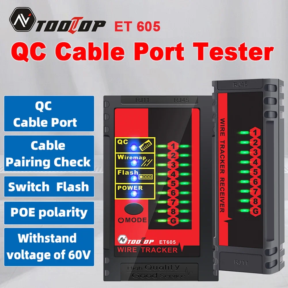
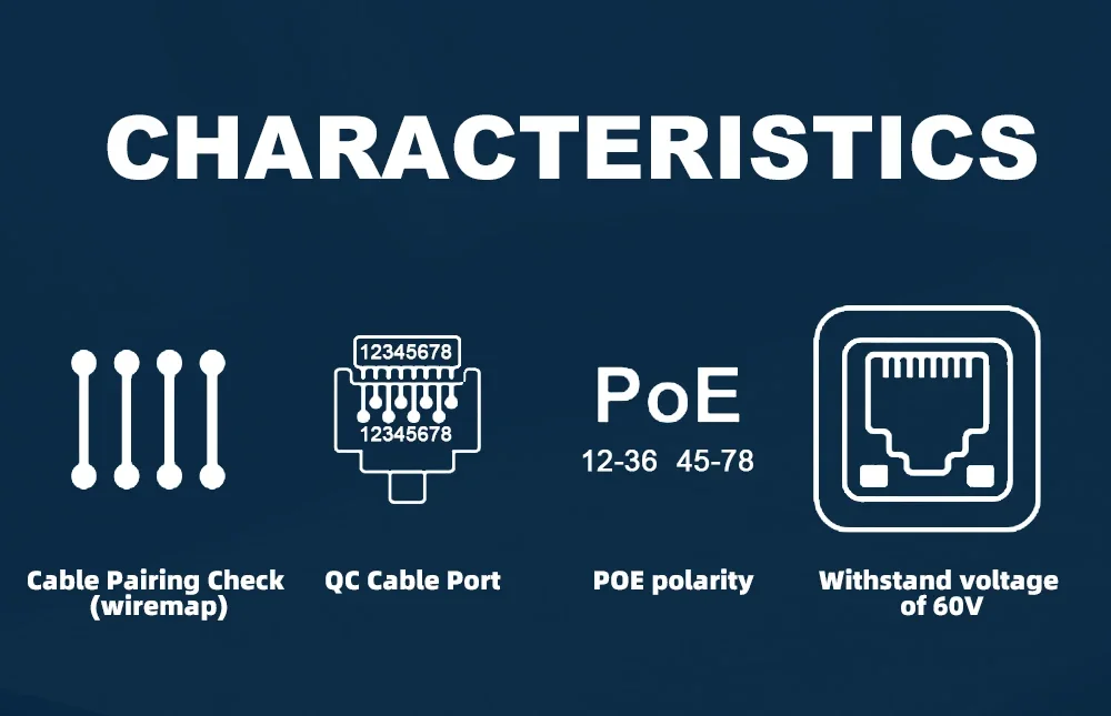
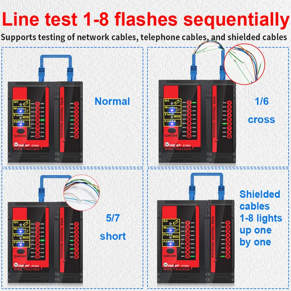
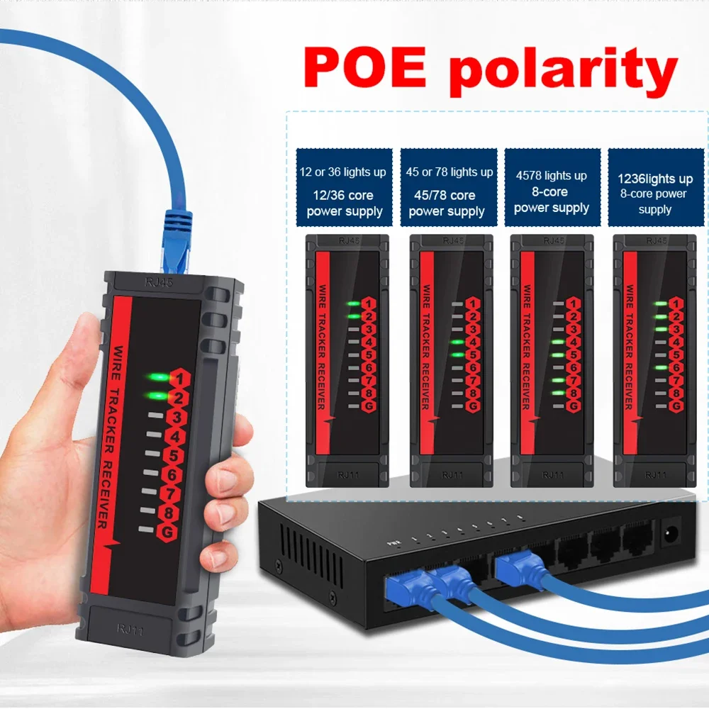
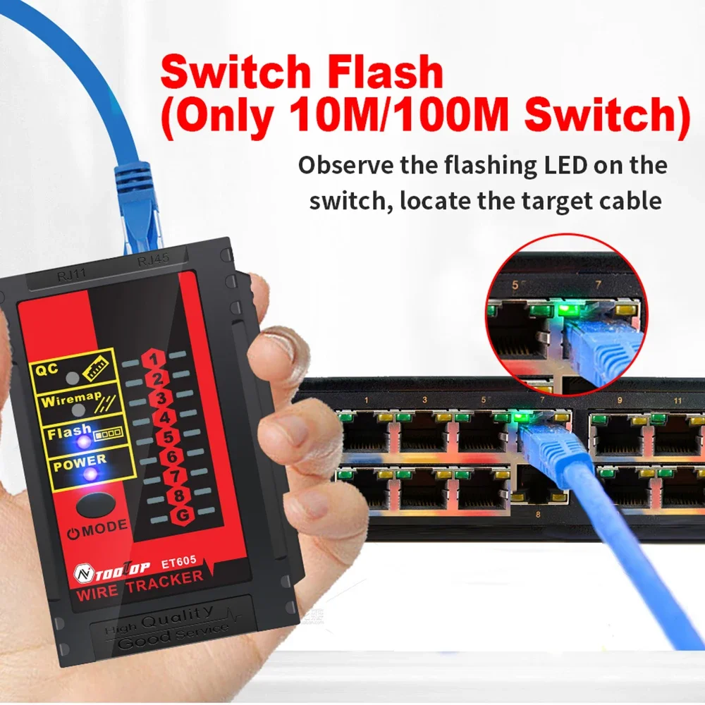
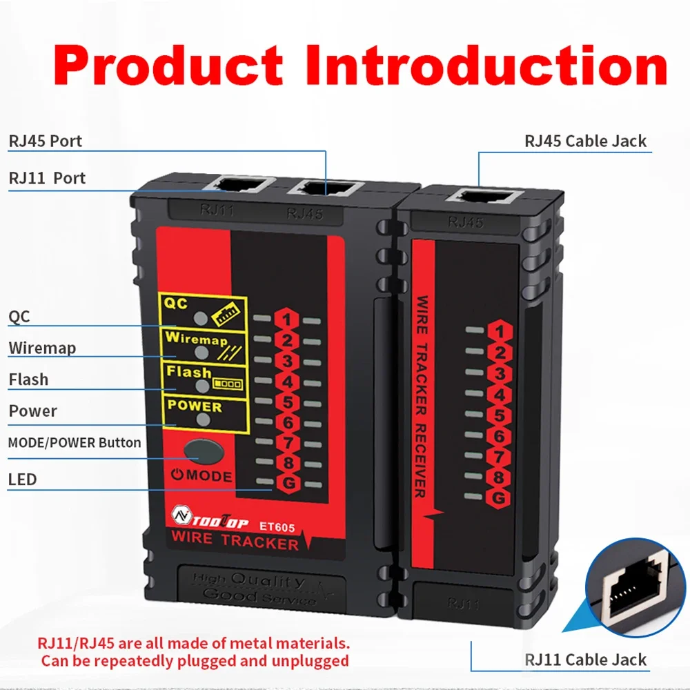
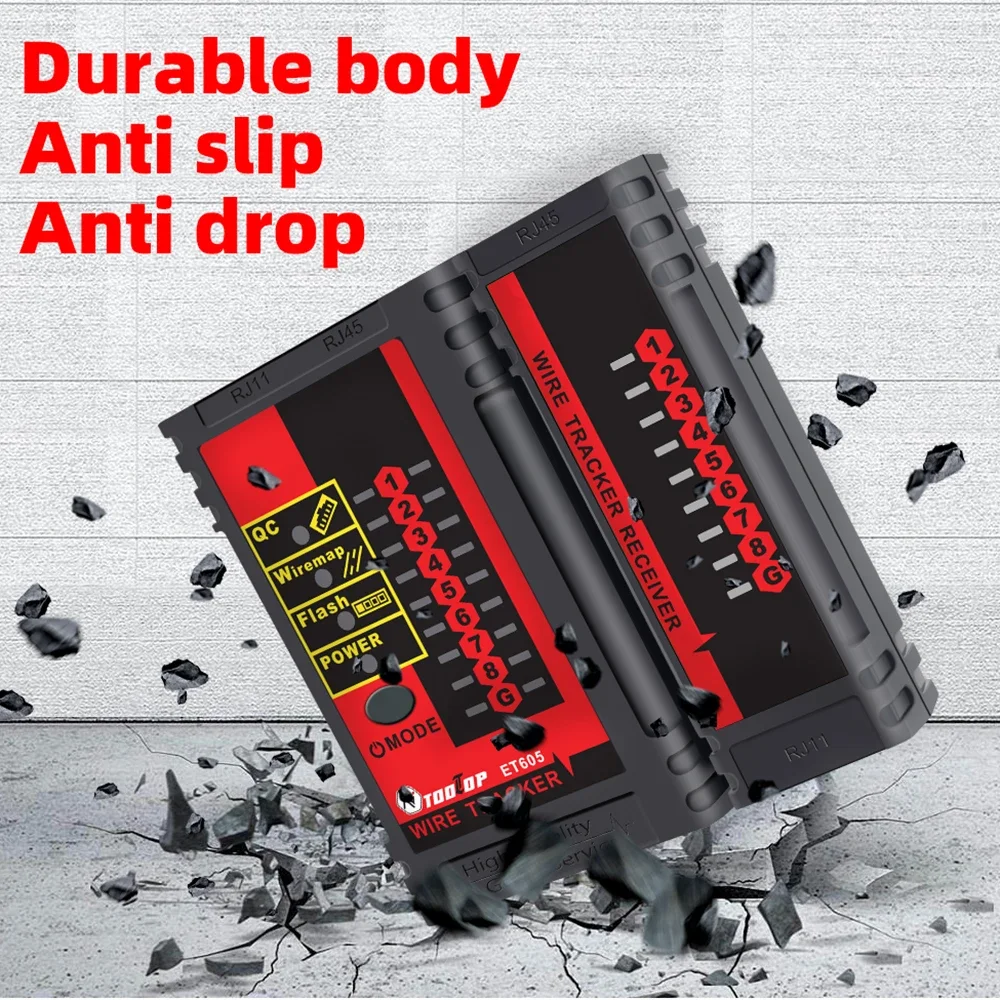
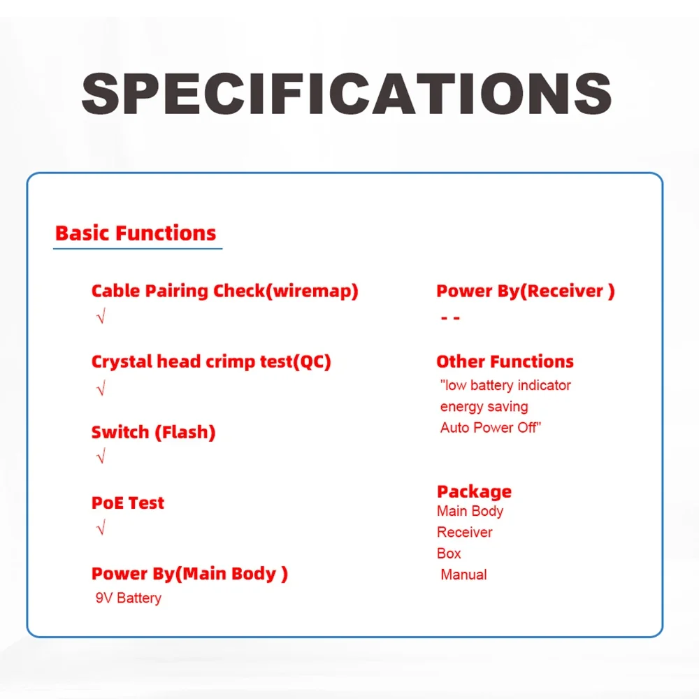
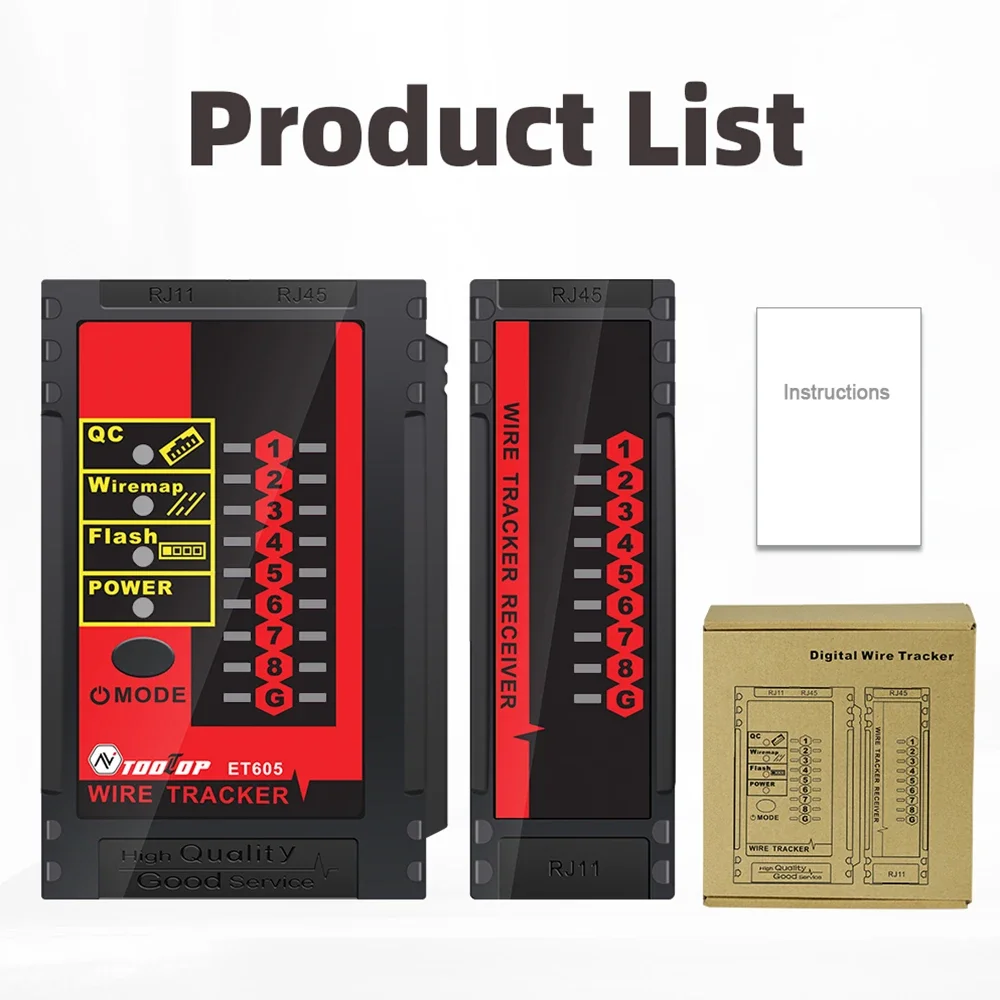


The TOOLTOP ET605 Network Cable Tester is a versatile network maintenance tool designed for installers, network engineers, electricians, and IT professionals. It combines cable pairing, RJ45/RJ11 crimp quality testing, PoE detection, switch port identification, and cable tracing into one compact device. With its user-friendly operation and portable design, the ET605 is ideal for troubleshooting, installation, and maintenance of LAN and telecommunication networks.
| Specification | Details |
|---|---|
| Brand | TOOLTOP |
| Model | ET605 |
| Device Type | Network Cable Tester |
| Cable Pairing Check | Supported |
| RJ45/RJ11 Crimp Test | Supported |
| PoE Test | Supported |
| Switch Port Flash Detection | Supported |
| Power Supply | 9V Battery (Not Included) |
| Battery Included | No |
| Other Functions | Auto Power Off, Low Battery Indicator |
| Origin | Mainland China |
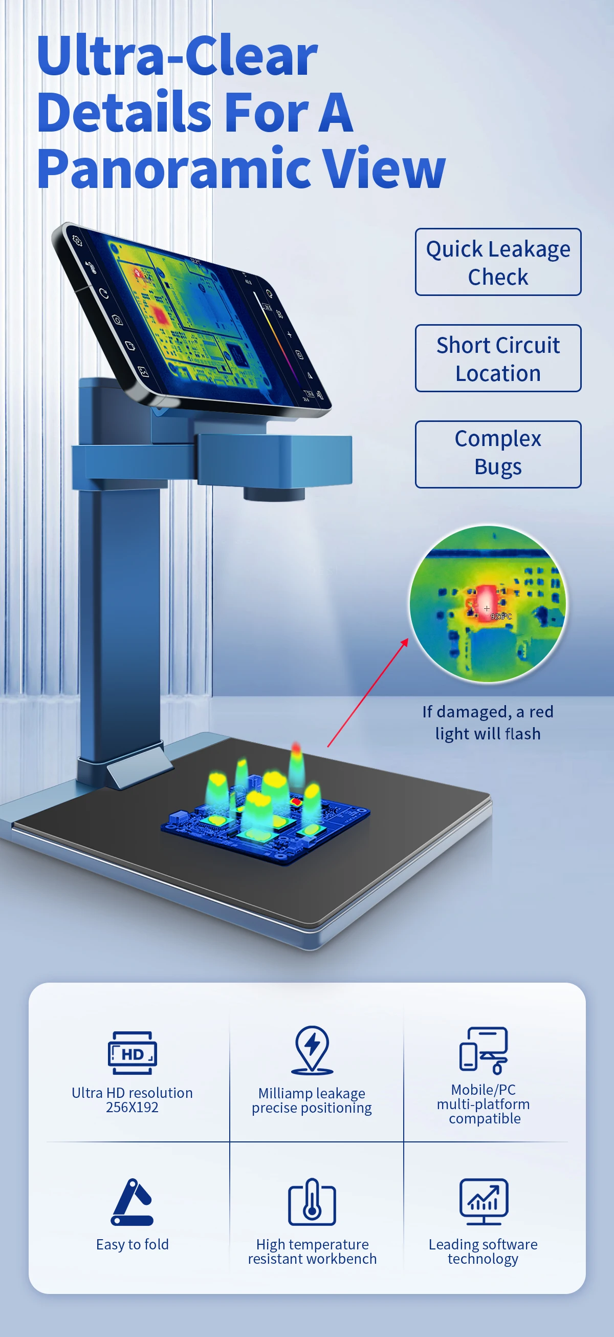
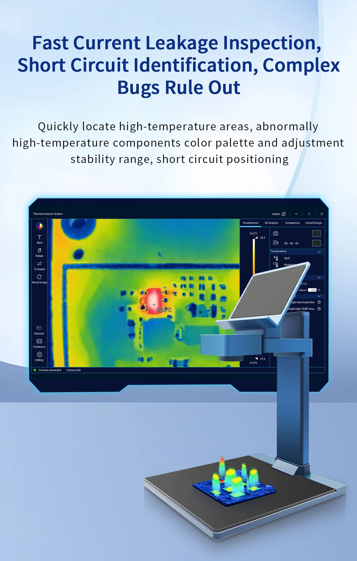
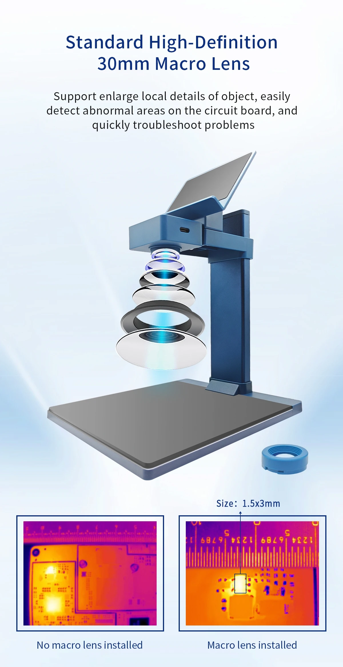
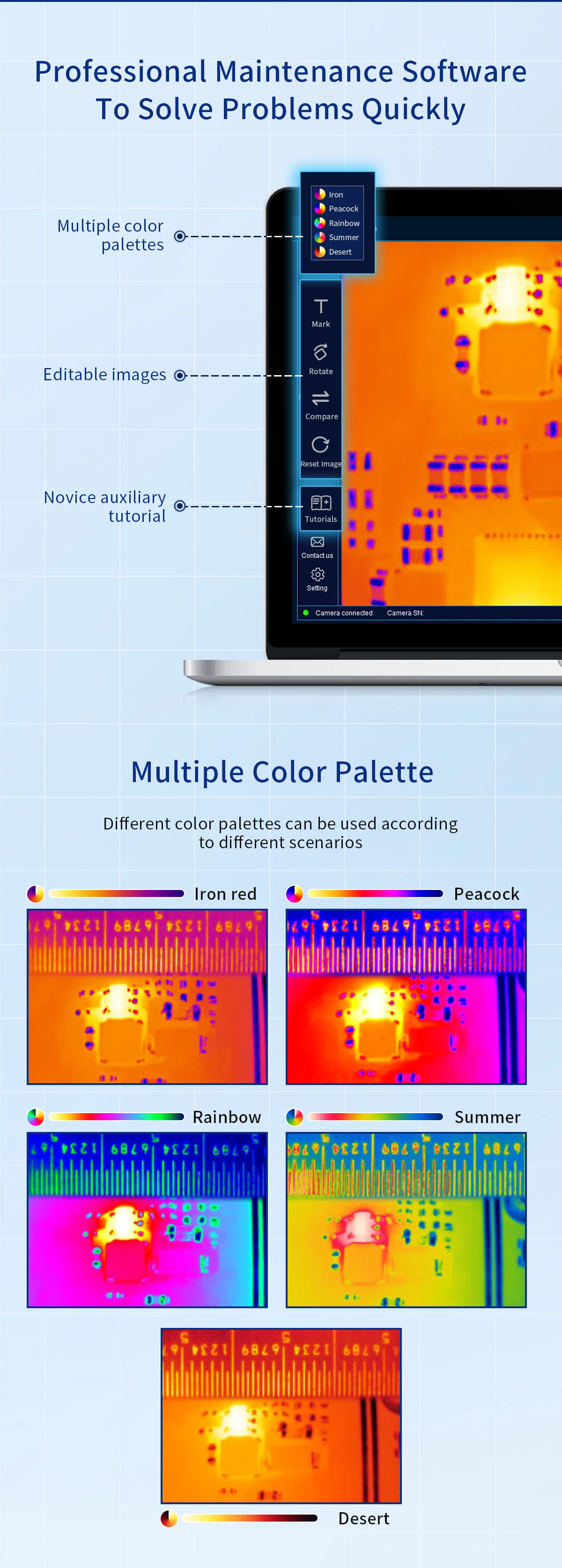
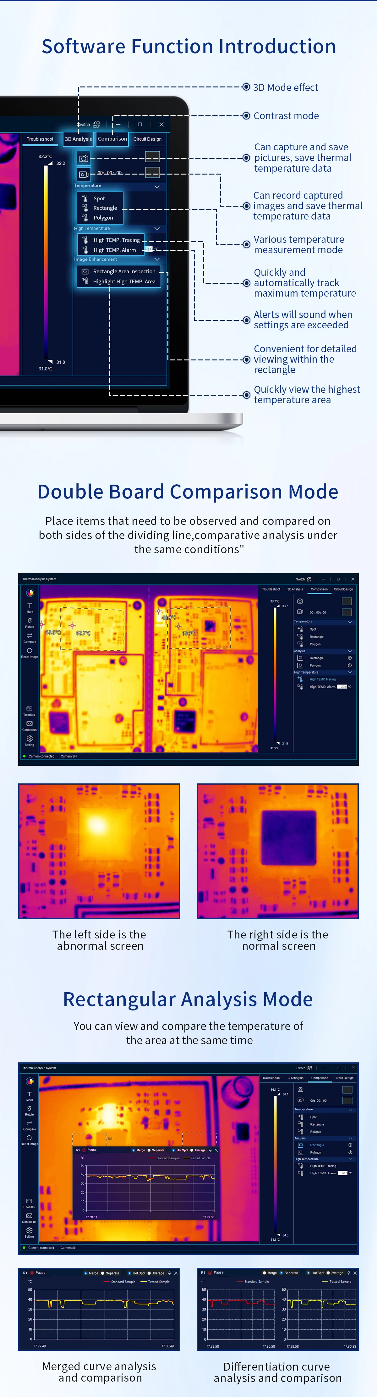
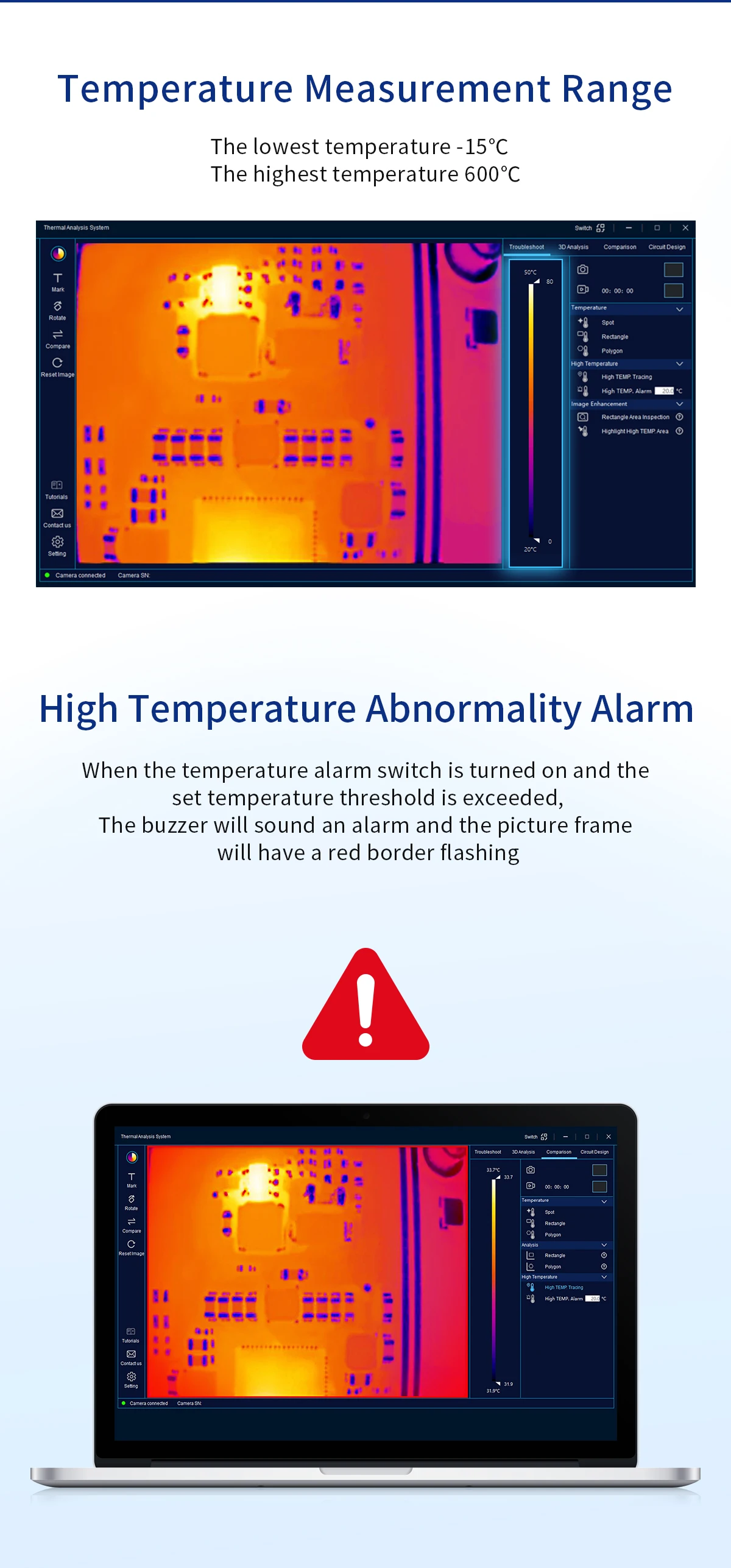
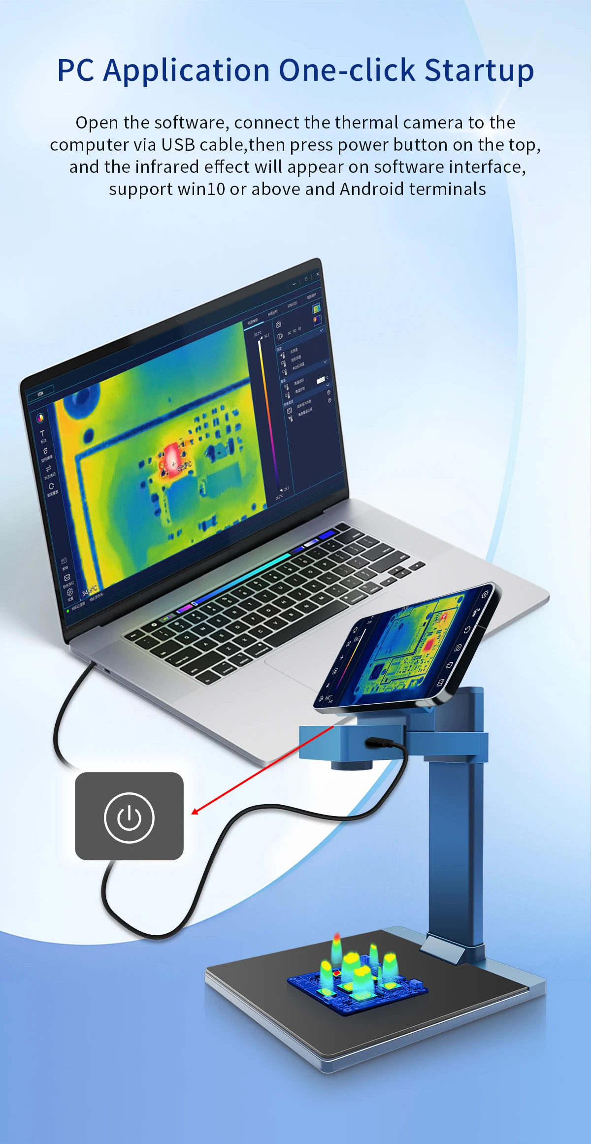
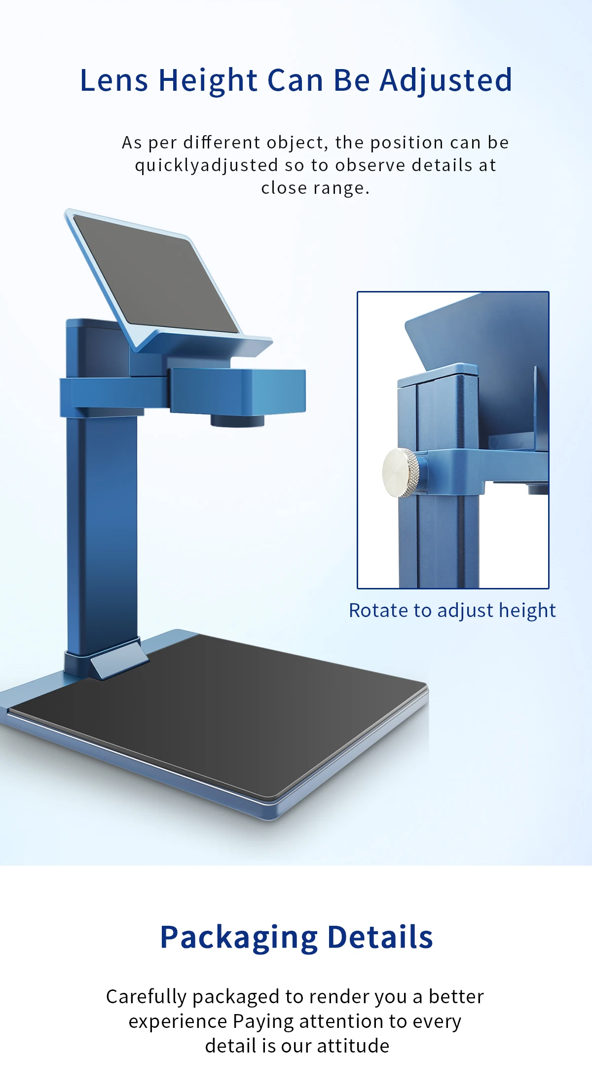
The TOOLTOP T210 Thermal Camera is a professional thermal imaging solution designed for PCB repair, electronic diagnostics, industrial maintenance, electrical inspections, and building analysis. Featuring a 256 × 192 infrared sensor, 25Hz refresh rate, and a 30mm macro lens, it delivers highly detailed thermal images for locating overheating components, short circuits, and hidden faults. Compatible with both Windows 10+ PCs and Android devices, the T210 offers powerful thermal analysis software with 3D imaging, multiple color palettes, image/video capture, and advanced comparison modes.
| Specification | Details |
|---|---|
| Brand | TOOLTOP |
| Model | T210 |
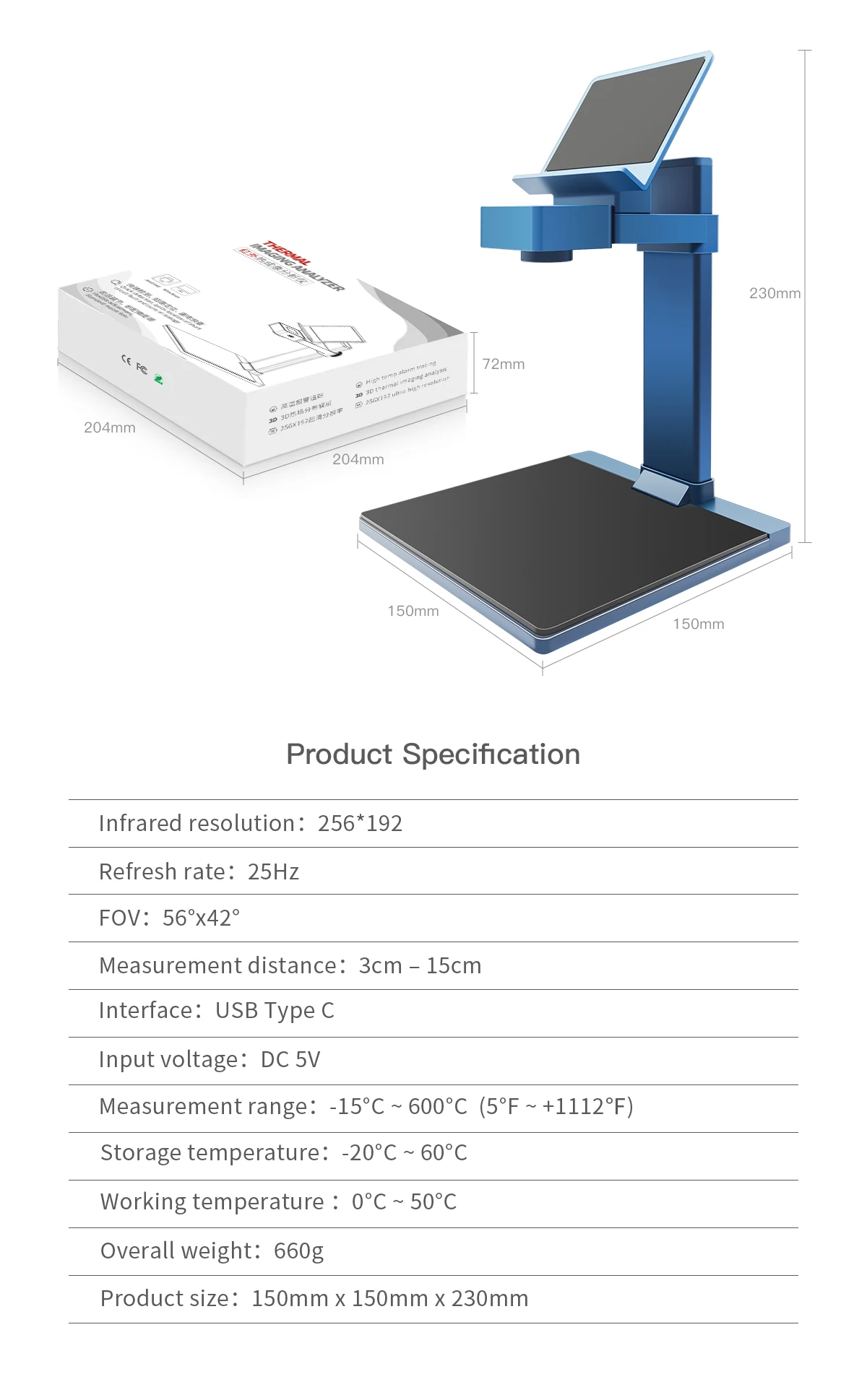
| Thermal Resolution | 256 × 192 Pixels |
| Refresh Rate | 25Hz |
| Temperature Range | -15°C to +600°C (-5°F to +1122°F) |
| Field of View (FOV) | 56° × 42° |
| Measurement Distance | 3cm – 15cm |
| Interface | USB Type-C |
| Input Voltage | DC 5V |
| Working Temperature | 0°C to 50°C |
| Storage Temperature | -20°C to 60°C |
| Software Compatibility | Windows 10 & Above, Android |
| Product Size | 150 × 150 × 230 mm |
| Overall Weight | 660 g |
| Battery Included | No |
| Origin | Mainland China |


TOOLTOP 2202 Multifunctional Tester User Manual SAFETY INFORMATION This series of meter fulfill IEC1010 (International Electrotechnical Commission). Please read the Safety Information before use. Read the technical specifications carefully. Only the model with multi-meter function is allowed to...
SAFETY INFORMATION This series of meter fulfill IEC1010 (International Electrotechnical Commission). Please read the Safety Information before use. Read the technical specifications carefully. Only the model with multi-meter function is allowed to measure DCV/ACV and Current with 36V or above. Never measure 36V or above (except PoE) if the model do not have multimeter functions. These voltages pose a shock hazard.
INTRODUCTION
This instrument is applicable to network cables CAT5, CAT5e, CAT6, CAT7,CAT8, RJ11, BNC, etc. This meter combines with the cable tracing cable length measuring and multimeter functions. The advantage of this meter is the long tracing distance, clear sound signals, rapid and precise cable length measurement, and accurate multimeter. The meter is good tools for laboratories, factories, radio lover, network installer, and technician, It can real time measuring network cable length, short circuit and circuit break. The cable tracing function can quickly and efficiently find out the telephone systems、computer networks、BNC cables and other metallic target cable in large number of cables This function can be used in network cables Our digital tracing apply the newest digital noise free technology. It give a good experience to users. The meter is essential equipment for computer networking, telecom cabling, BNC cabling and other metallic cabling projects.
WORKING PRINCIPAL Cable length measurement is performed by sending a signal to one of the wire in the cable. By receiving and calculating the reflected pulse to get the cable length. By sending a signal from the MAIN port to the target cable, an analogue signal field will be generated. The receiver will identify the signal field and find out the target cable.
CHARACTERISTICS
PRODUCT INCLUDE
EQUIPMENT OPERATION
Tracing Cables (SCAN) | Find out the target cable in numerous cables. |
Cable Pairing Check (TEST) | Test open circuit, short circuit and cable mapping |
V (VOLT) | Check the polarity and voltage of battery/phone line |
Continuity Test (OHM) | Check open circuit or short circuit of phone line (phone line should not be connected to any power source) |
ID Pairing | Able to check Network Switches and Cables by connecting one end to the Remote ID unit |
PoE Test | Checking cable mapping and voltage/polarity of PoE Network Switches |
Flashlight | White flashlight |
Sensitivity Adjustable | Able to adjust the sound level |
Length Measurement | Able to measure cable length, short circuit and circuit break |
Cable Tracing Signal Changable | Two kinds of analog signal frequencies for wire-tracing |
Multimeter | Have DCV, ACV, Continuity, Diode, Voltage, Cap, NVC, Resistance, DCA, DCV and Live Test |
QC Cable Port | Qulity verify the crimping crysta Port (RJ45/RJ11) |
PRODUCT DESCRIPTION
 PRODUCT INFORMATION
DIGITAL CABLE TRACING Product is a noise free digital wire tracker. The product apply the advance digital technology to achieve precious digital noise free cable tracing. Following is the comparison of digital wire tracker and analogue wire tracker.
Operation: he operation method of the host is the same, but the operation method of the digital line finder is different from that of the analog line finder. The line finder can be powered on by pressing and holding the MODE button for 2 seconds, and turned off by pressing and holding the MODE button for 2 seconds. If there is no operation for 10 minutes, it will automatically shut down. After the line finder clicks MODE to select the function, it can perform the line search operation. The host enters the line search function, that is, the digital line search mode. To quickly find the target line, you can first adjust the direction knob of the line finder to the maximum sensitivity. After finding the vicinity of the target line, adjust the appropriate sensitivity to accurately locate the target line; at this time, you can connect the target line to the RJ45 port of the line. finder, and the line lights are all on to further confirm that the target is correct.
Digital line search function: (blue indicator light) Using the latest digital line search technology, the host sends a digital signal, and the line finder tests by receiving the digital signal transmitted on the tested network cable and sends a corresponding sound (the blue indicator light is on) or vibration (the blue indicator light flashes);
MEASURING CABLE LENGTH (LENGTH) After turning on the power, the product enters the length measurement function. Press the input indicator on the LCD to connect the network cable to be tested. The product LCD will display "----" in a loop. After inserting the network cable, the product will complete the test in 2 to 5 seconds, and the test results will be displayed on the screen. At the same time, the line status (1\2\3\4\5\6\7\8) is displayed. The user can read the quality of the line and measure the length according to the display; when measuring the network cable, the other end of the network cable cannot be connected to any device. Click the key to switch the length of the 12/34/56/78 line; Click the MODE key, and the product will switch to display the length iFt; The length measurement range is 2.5~400M; 
FLASH This function can drive the LED of the network switch to flash, so as to determine the specific port of the target cable; The two ends of the network cable are respectively inserted into the host and switch ports. Under the signal drive of this product, the corresponding LED light of the switch port will flash at intervals of about 3s. Users can determine the target by observing the LED on the switch; Applicable to 10M/100M/1000M switches.
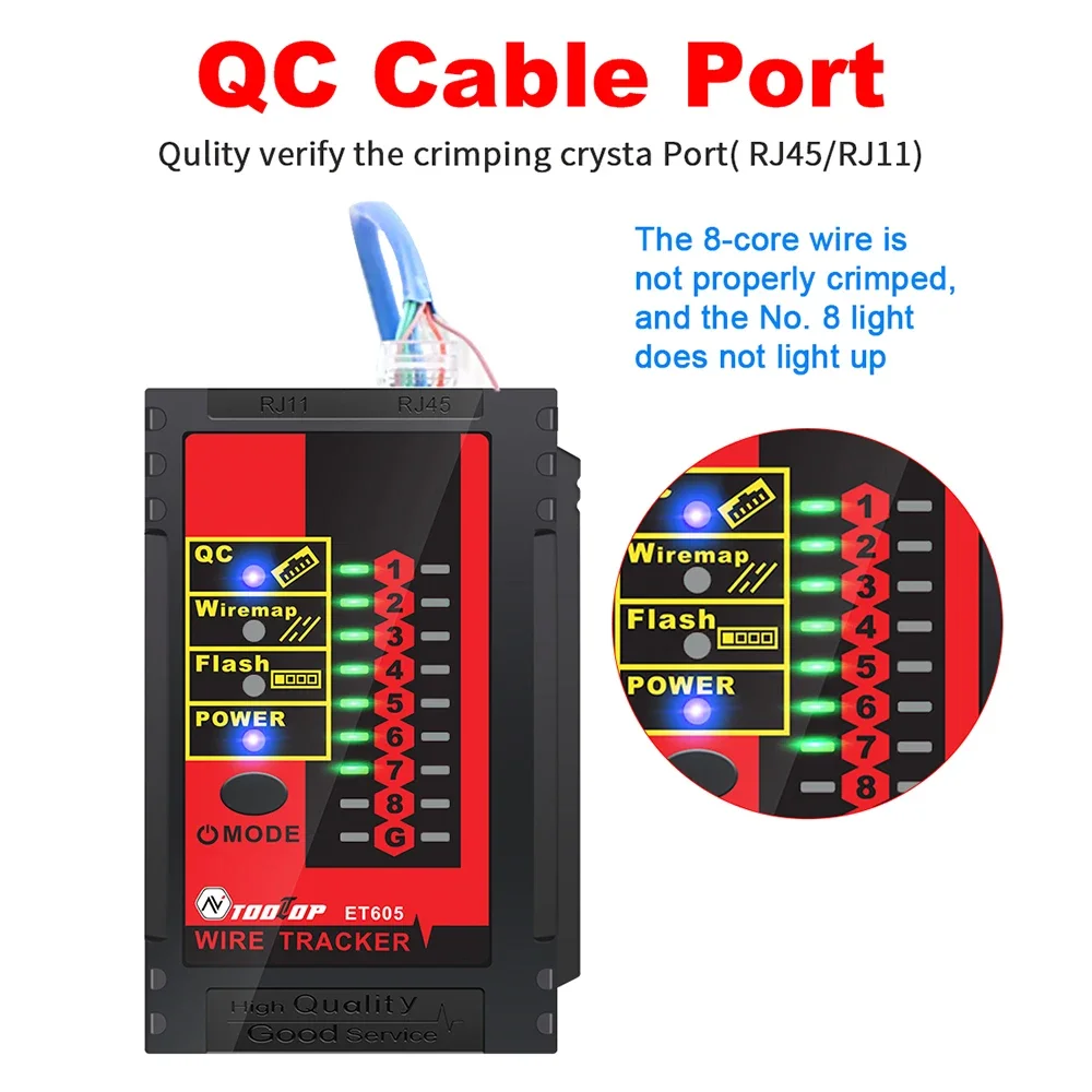
QC (Qulity verify the crimping crysta Port) The cable crimping detection function can detect whether the production of RJ45/RJ11 ports is qualified or unqualified
Operation Click MODE to switch and select the crystal head test function; Insert one end of the cable to be tested into the MAIN interface, and the other end of the cable is unloaded. No device needs to be connected. At this time, enter the wire crimping test state. The test results are shown as follows:
ID TEST ID Not a standard accessory
Operation Click the MODE button and select the ID TEST remote identification function; Connect one end of the network cable to the optional ID identifier and the other end to the host MAIN port. The host LCD will immediately display the corresponding ID number, thereby achieving accurate identification of the network cable;
CABLE MAPPING (TEST) Cable mapping function, test the conditions such as open circuit, crossover and short circuit of the network cable. 
Operation Click the MODE key to select the TEST function. Connect one end of the line to the MAIN socket and insert the other end into the RJ45 socket. The result is displayed on the LCD.
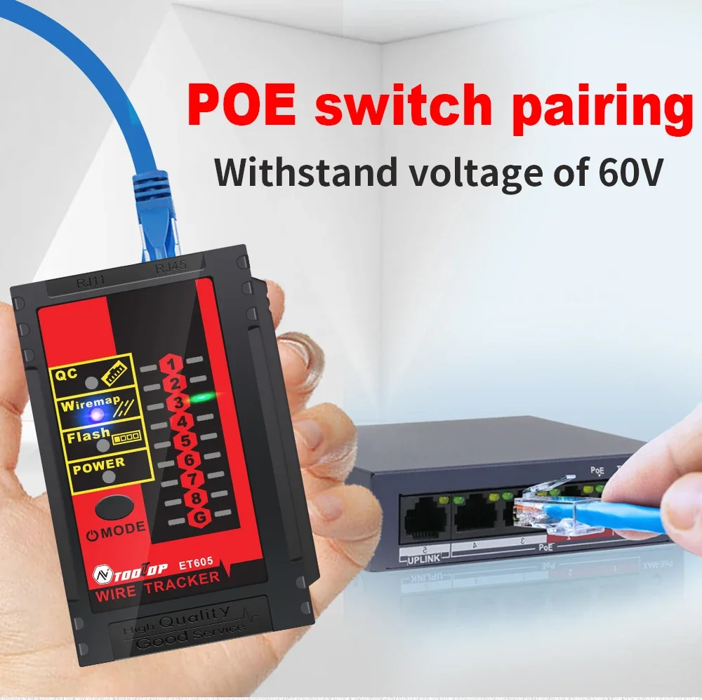
Switch pairing
Operation key, the When the TEST function is in use, click the product enters the switch line function, and "HUB" is displayed on the LCD. Connect one end of the line to be tested to the MAIN socket of the transmitter and the other end to the switch port. At this time, the product will test the network cable and display the result on the LCD. 
POE TEST The PoE voltage measurement function of the product can measure and analyze the power supply of the PoE power supply device and test the basic conditions of the POE device, including the power supply voltage and the positive and negative of the power supply line.
Note: After connecting the PoE device, the result can be displayed after a few seconds. If the result is not displayed after 30 seconds, the connected device may not be a PoE device. The actual output voltage of POE will be different from the nominal voltage, which is normal. 
Operation Press the MODE button and select POE. Connect the network cable to the host socket according to the product input prompt, and connect the other end to the PoE power supply device. The product will detect the device and enter the corresponding communication as needed and display the test results; for non-standard PoE, it will directly measure and display the power supply voltage.
MEASURING LOW VOLTAGE (VOLTAGE) This function can test some basic voltage conditions of the line, including the presence or absence of line voltage and the positive and negative voltage. Insert one end of the alligator clip adapter cable/RJ11 telephone cable into the transmitter's socket, and clamp the red and black wire clips on the line to be tested. If there is voltage on the telephone line, the LCD will display 3 and 4 long connection lines, and the positive pole will flash. If not, 3 and 4 are short connection lines. (Warning: AC and other high-voltage circuits cannot be measured, otherwise there is a risk of electric shock) 
Operation Press the MODE button and select BATT V MODE. Use crocodile clip cables to connect phone lines or batteries. Will display voltage and polarity (flashing positive),
NCV TEST
Operation NCV electric field detection function, which can sense the presence of voltage in the circuit. During testing, place the top of the product close to the tested circuit and use sound to determine the strength of the voltage. 
CABLE TRACING (SCAN) The line-finding function of the product is mainly to quickly find the required target line among many line pairs. Connect one end of the line to be tested (such as network cable, telephone line and video signal line that can be transferred by alligator clip) to the MAIN socket of the transmitter, turn on the transmitter, press the MODE button, switch to the SCAN line-finding function, and the product enters the line-finding signal transmission state. Press the mode button of the receiver for 2 seconds to turn on and enter the line-finding function state (the blue light is digital line-finding), and listen to the "beep" sound emitted by the receiver speaker around the other end of the line to be tested (such as the line terminal, the wiring rack of the telephone system, the junction box, and the hub end of the computer network). Compare the size of the "beep" sound, and the line that emits the loudest "beep" sound is the target cable to be found.
Operation After powering on, click the MODE button to enter the line SCAN function. At this time, you can connect the network cable to the host MAIN or connect other metal lines through alligator clips. Press the line finder MODE button to enter the blue digital line search function. The target line can be judged and determined by the sound volume; 
CONTINUITY TEST (CONT) The function is to test the short circuit of a phone line which is not plug in any networks. Ensure the phone line is not powered before testing. Insert the cable into the main jack for testing, or use the provided alligator clips to connect the cable for testing This function can also apply to test the continuity of other equipment The LCD screen will display whether the cable line is in a conducting path or in an open circuit. 
Operation Press MODE button to select the CONT function.the display screen prompts Ω Use the alligator clips to clamp the network cable/wire/coaxial video cable, etc. If the line is a conducting path, the screen will display 02. If the line is an open circuit, the screen will display OL.
TROUBLE SHOOTING
Main Body Symptoms: Display is not on or flashing after pressing the Power button Reasons: Battery gone Solutions: Charging the Main Body or replace the battery (protected 3.7V lithium battery)
Receiver Symptoms: Press SCAN button but no sound is generated during cable tracing Reasons: Battery gone or No battery or Receiver is too far away from the target cable Solutions: Change battery or enlarge the searching area
OPERATION MANUAL Following instructions are only applied to the model with multimeter functions.
1.1 Voltage Measuring
Cautions a. If OL is displayed, the measuring voltage is over ranged. Please stop measurement. b.It is not allowed to measured voltage over 1000V DC or 600V AC. c. Do not touch the Hi-voltage circuit, never connect network cable, live wire or charging cable when measuring Hi-voltage.
1.2 Current Measuring
Cautions
a.If OL is displayed, the measuring current is over ranged. Please stop measurement. b.It is not allowed to measured current over 10A (measuring time less than 10 seconds)
1.3 Resistance Measuring
Cautions
a. If OL is displayed, the measuring resistance is over ranged. b.OL will also be displayed if the testing object is an open circuit. c. Ensure the testing object is removed from energized circuit and/or fully discharge before measurement. d. Do not input voltage in the resistance range. e. For high resistance measurement (> 1M), it is normal for taking several seconds to obtain a stable reading.
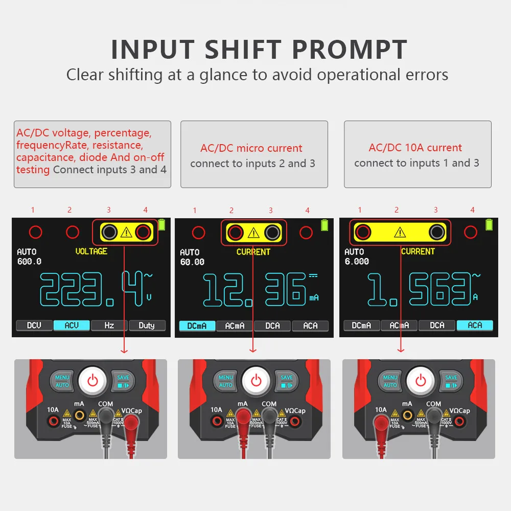
2.1 Testleads connection The product have input jack indicators to remind users to plug-in the correct jacks. Mis-plugging the leads may damage the product and/or hurt the users. Please ensure the connection is correct before measurement.
Indication of testleads connection for DC/AC Voltage/Resistance/Diode/CAP Measurement Indication of testlead connection for 10A DC/AC Current Measurement 
CHANGING BATTERIES/FUSE Changing Battery in the Main Body
Changing Battery in the Receiver
Auto Power Off Main Body: Automatically switch off for about 20 minutes Receiver: Automatically switch off after for about 10 minutes
Current Main Body: 40 sim 130mA (subject to the functions) Receiver :<= 100mA
Powered by Receiver: 9V laminated battery Main Body: Have protected funtion 3.7V lithium battery Cable Tracing Signal Transmission Distance about 3km
SPECIFICATIONS
Functions | Basic Upgrade |
Cable Length | 2.5-400M network cable / <20M±1 .5M 20-100M±2.4M /100-200M±3.2M / >200m reference |
Digital Tracing | Digital Digital /Vibration |
Cable Mapping | Normal/Open/Short/Cross |
QC.crimping | |
Continuity/Batty | |
FLASH(HUB/Switch) | 10M/100M/1000M |
POE Volt TEST | Voltage/polarity |
Remote ID | Optional functions ID1-15 |
NCV Detection | |
DMM | |
DCV | 6.000V-1000V (±0.5%+3) |
ACV 1 | 6.000V-750V (t0.8%+5) |
DCA | .9mA-9 999A(ti /o+4) |
ACA | 999.9mA-9.999A(±1%+5) |
R | 600.00-60 m0(±1%+6) |
CAP | 6.000nF-666.6uF±(2.0%+6) 6.000mF-60. 00mF±(5%+20) |
Continuity | < 100 |
Diode | |
FLUSE | CE 5*20MM 10A/1000V |
Live | |
OTHER | Host lighting function, input hole prompt function VA display, white light flashlight function,Digital line search sensitivity adjustable, low voltage detection |
Package | Color box/manual/RJ45 cable/USB cable alligator clip cable/test lead (only for Upgrade) |
Power | 1250mA.H(host)rechargeable lithium battery, (with protection circuit),9V(receiver) Charging requires a 5V/2A/10W charger or above (not included) Host: Charging time is about 2 hours, and the battery is fully charged and works for about 4 to 6 hours |
*Indicators are the best indicators of function
QC PASS QUALIFICATION CERTIFICATE
PRODUCT MAINTENANCE Maintenance
This product is a pre equipment. Please ensure the battery power is good. Follow the instructions, especially to ensure the multimeter input jack is plug in correctly. User is not allowed to change the connection. Otherwise, the product may be damaged and the user may get hurt. Please follow the instruction to maintain the product:
Trouble Shooting and Warning
If the product cannot work properly, please check the battery, fuse or the power switch. Please have the product serviced if the problems cannot be solved. All information provided is subject to change without prior notice. We tried our best to keep the information most updated and correct. If user find any mistakes, and/or information missing, please contact us or your distributor. Our company is not responsible for all damages or hurts caused by the incorrect operations. All the functions mentioned should not be used as a reason for special purposes.


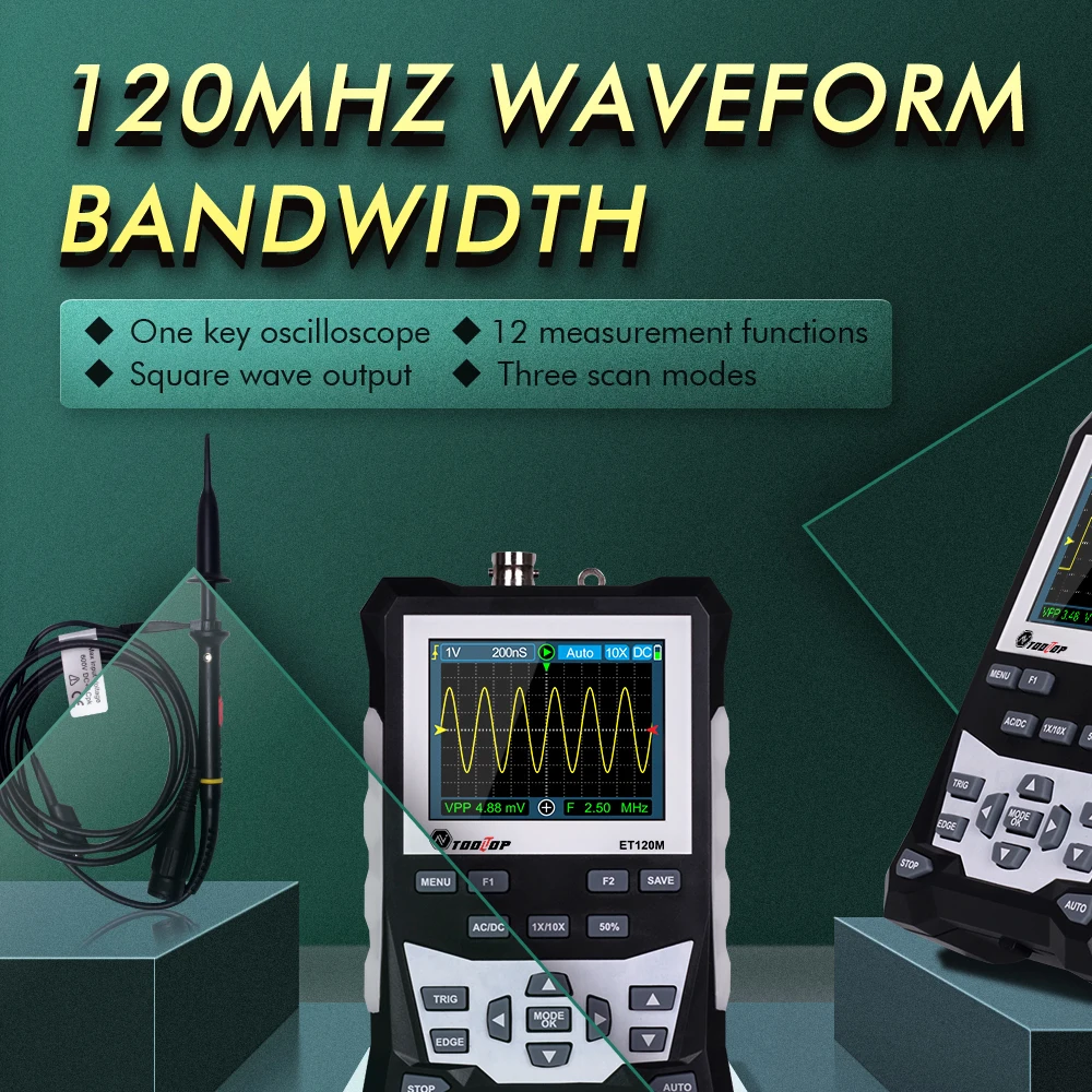
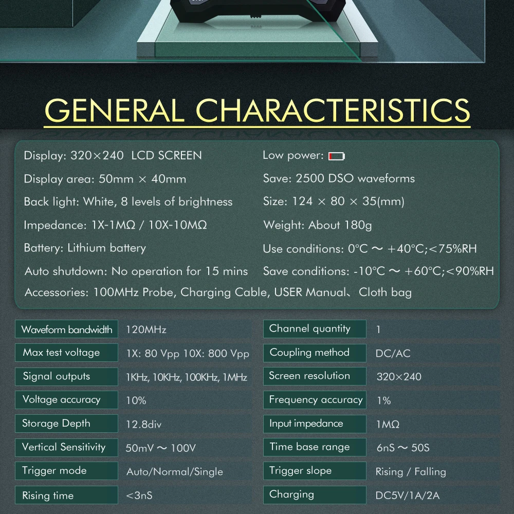
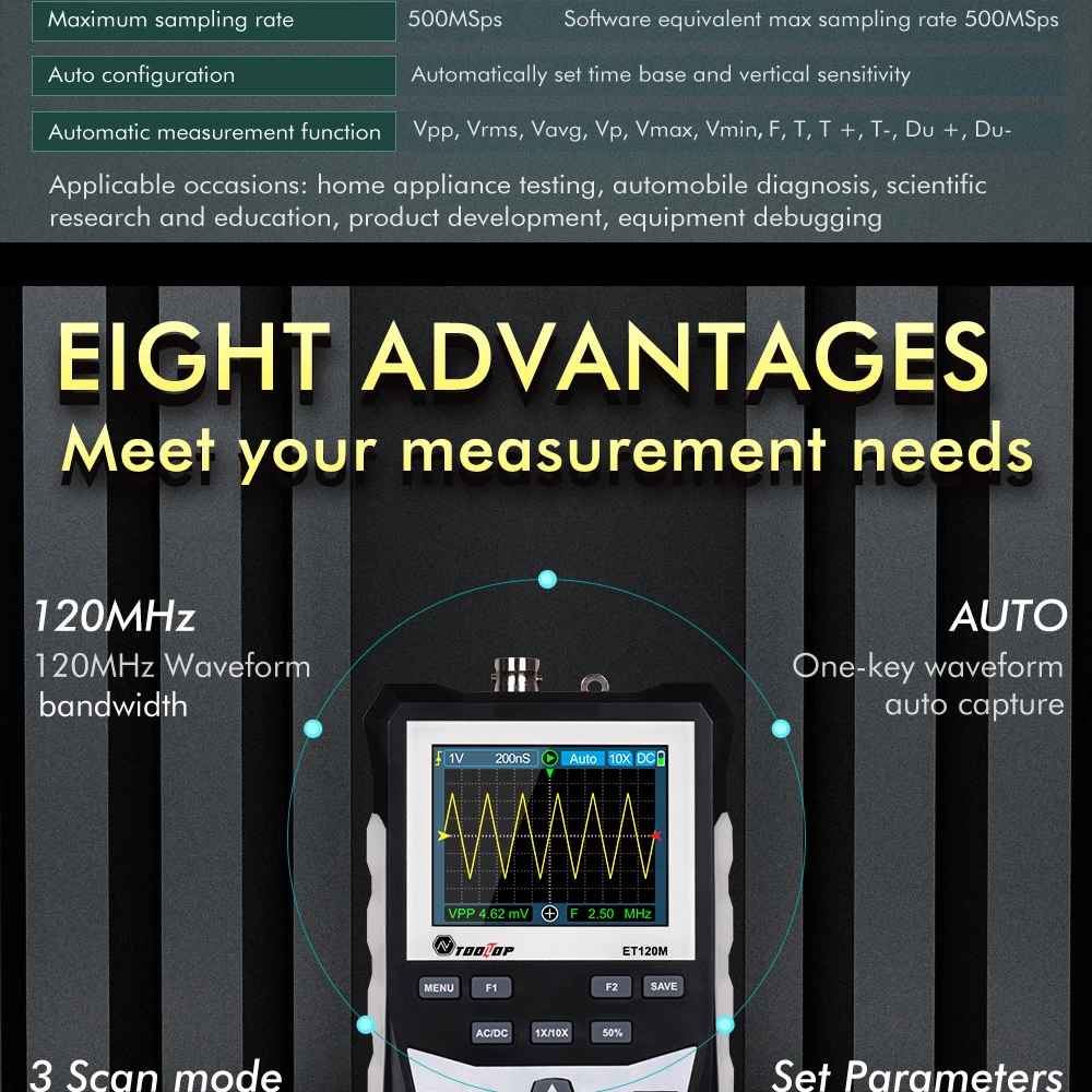
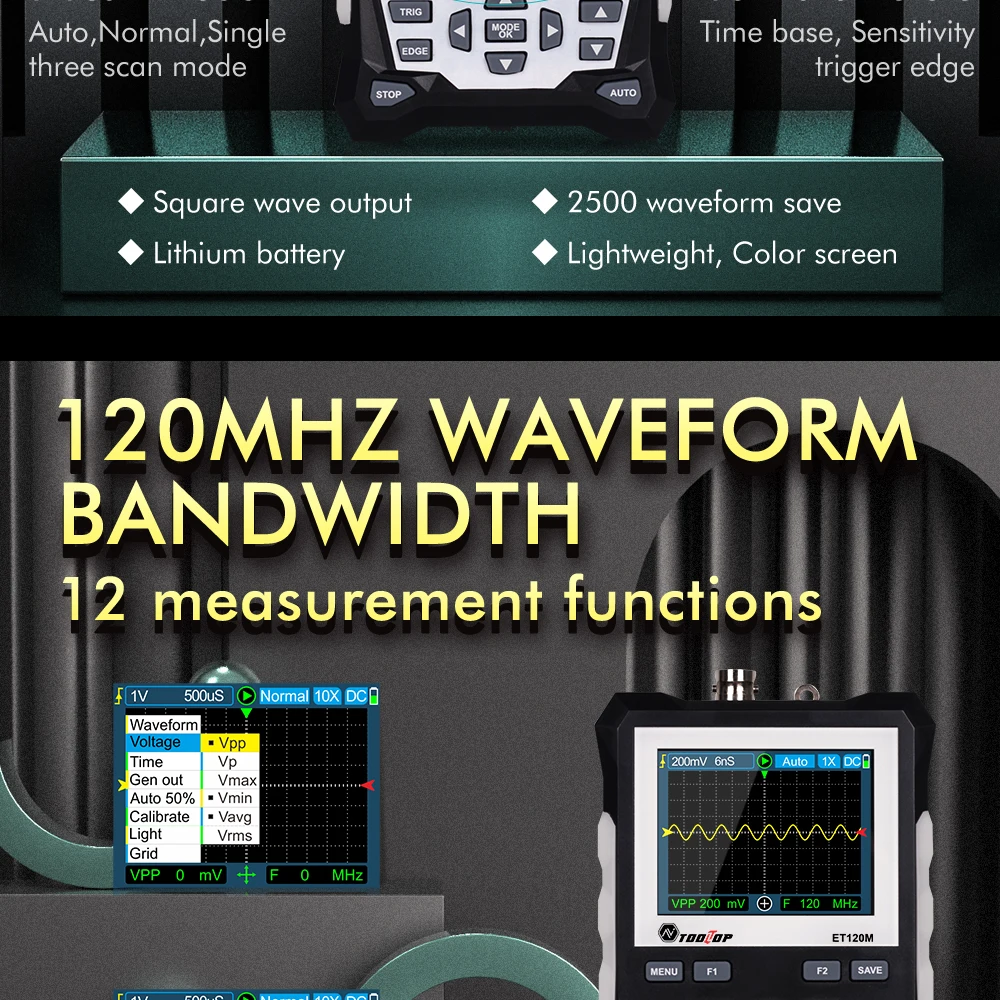
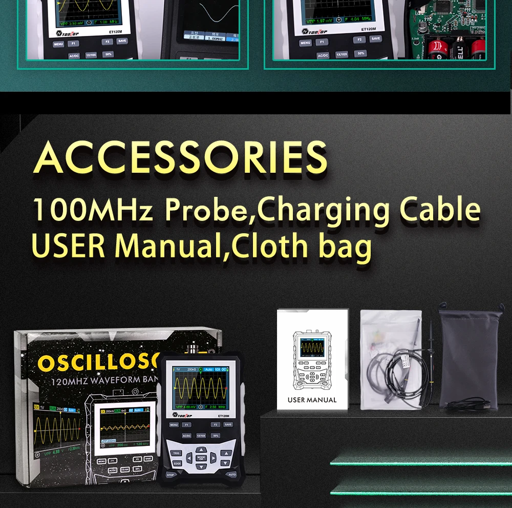
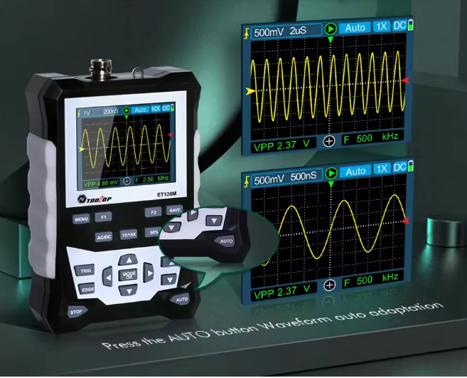
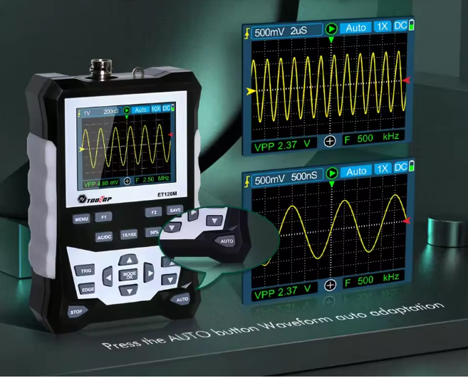
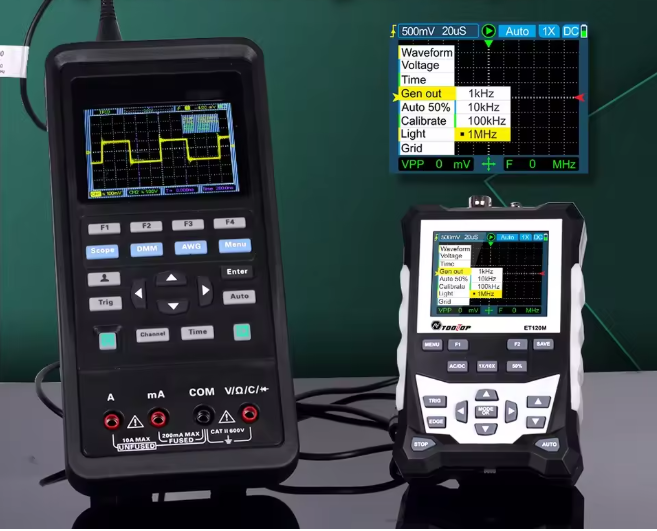
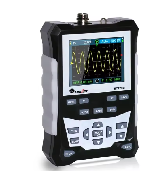
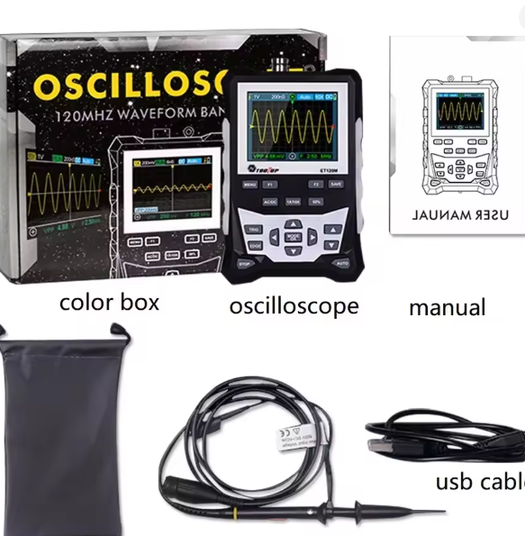
The TOOLTOP ET120M is a compact handheld 120MHz Digital Oscilloscope featuring a 500MSa/s real-time sampling rate, 2.4-inch color LCD, rechargeable 18650 lithium battery, and waveform storage. It is ideal for electronics repair, automotive diagnostics, laboratory testing, educational use, and field maintenance.
| Specification | Details |
|---|---|
| Brand | TOOLTOP |
| Model | ET120M |
| Product Type | Handheld Digital Oscilloscope |
| Bandwidth | 120MHz |
| Sampling Rate | 500MSa/s |
| Channels | 1 Channel |
| Display | 2.4-inch 320 × 240 Color LCD |
| Vertical Resolution | 8-bit |
| Waveform Storage | 2500 Waveforms |
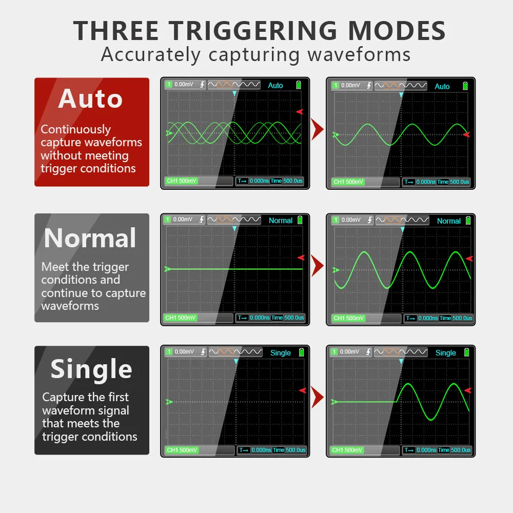
| Trigger Modes | Auto / Normal / Single |
| Trigger Slope | Rising / Falling |
| Coupling | AC / DC |
| Input Impedance | x1: 1MΩ / x10: 10MΩ |
| Time Base Range | 6ns/div – 50s/div |
| Vertical Sensitivity | x1: 50mV/div–10V/div x10: 500mV/div–100V/div |
| Battery | Rechargeable 18650 Lithium Battery |
| Auto Power Off | 15 Minutes |
| Operating Temperature | 0°C – 40°C |
| Storage Temperature | -10°C – 60°C |
| Dimensions | 124 × 80 × 35 mm |
| Weight | 280–350 g (Approx.) |
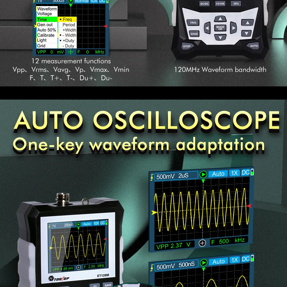
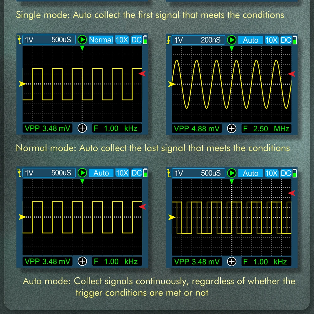
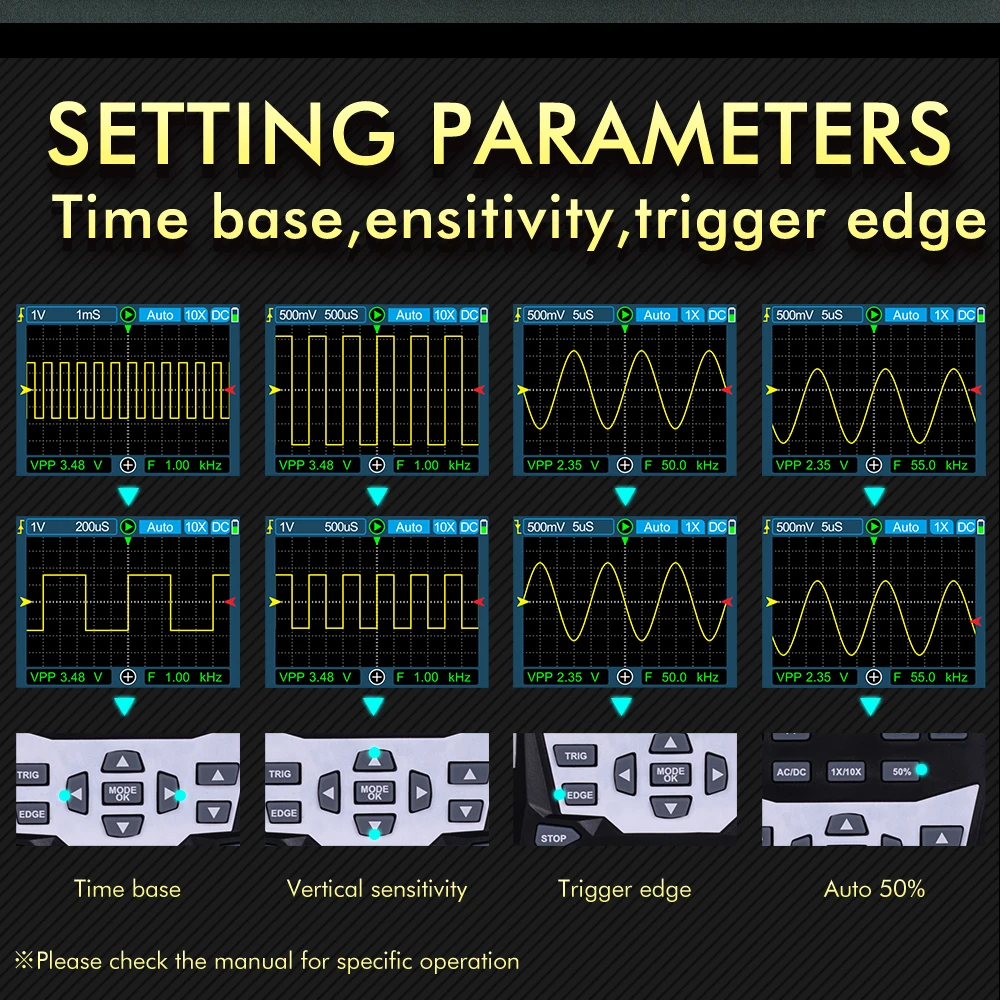
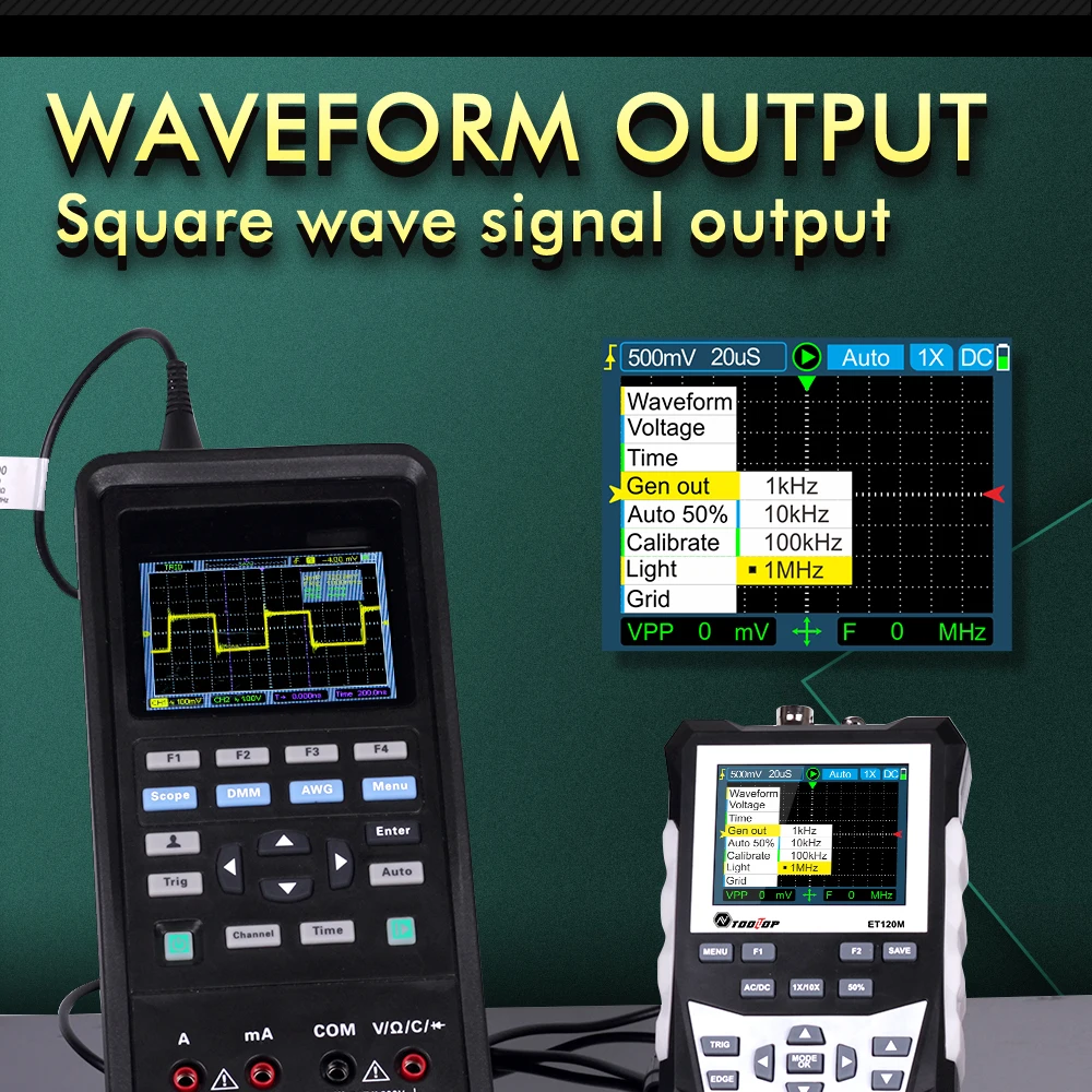
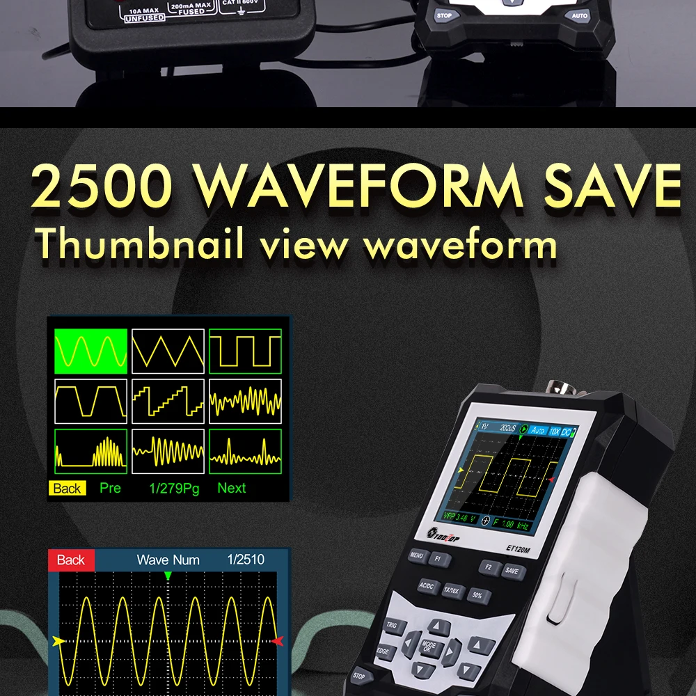
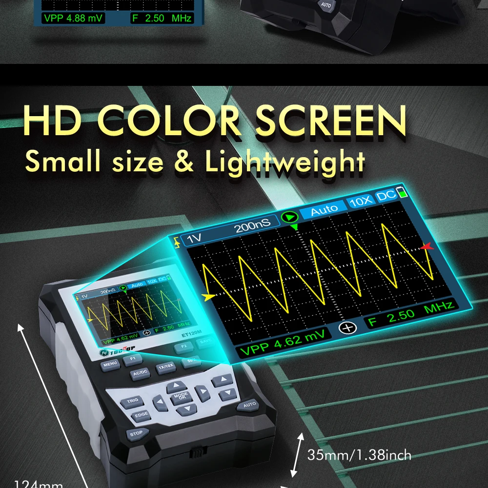

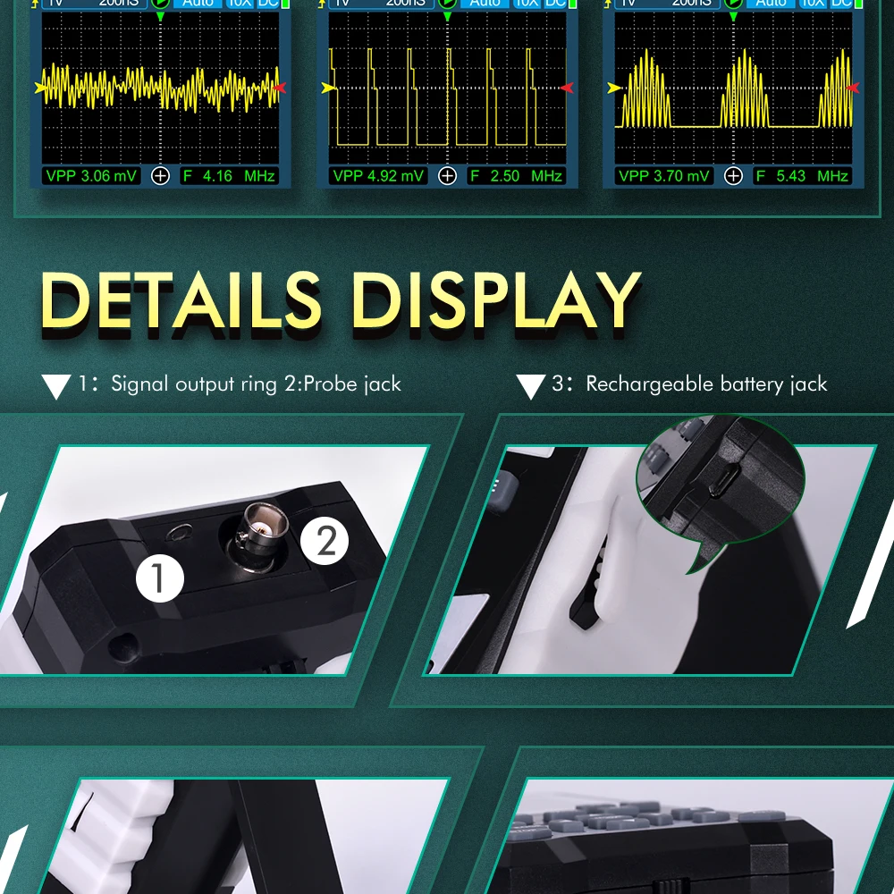
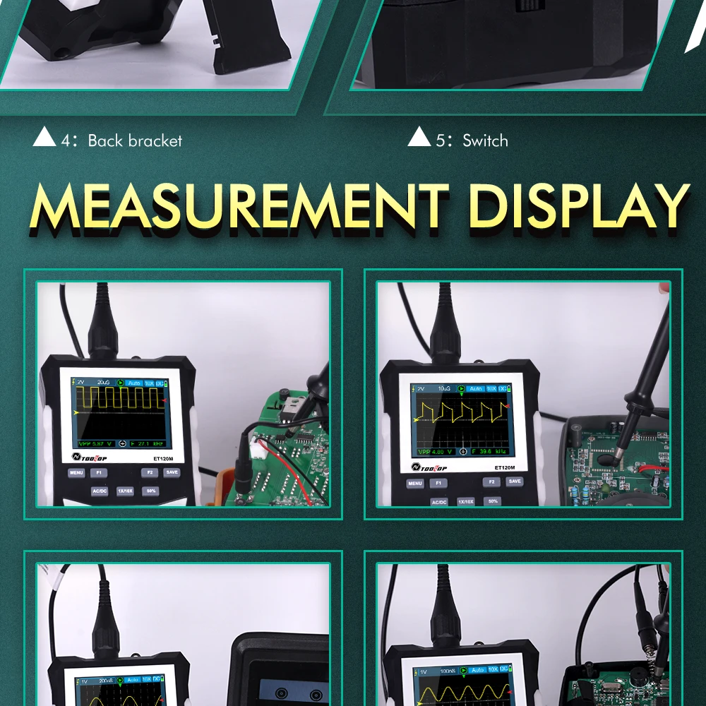
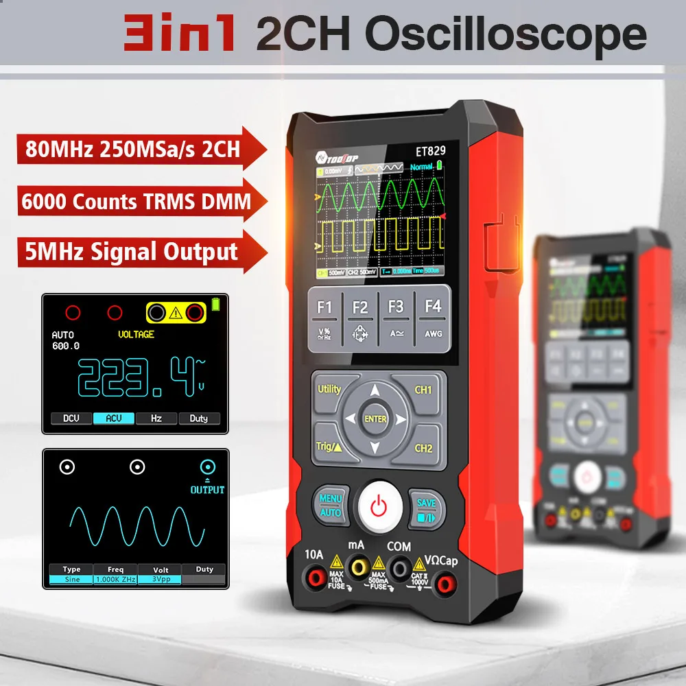
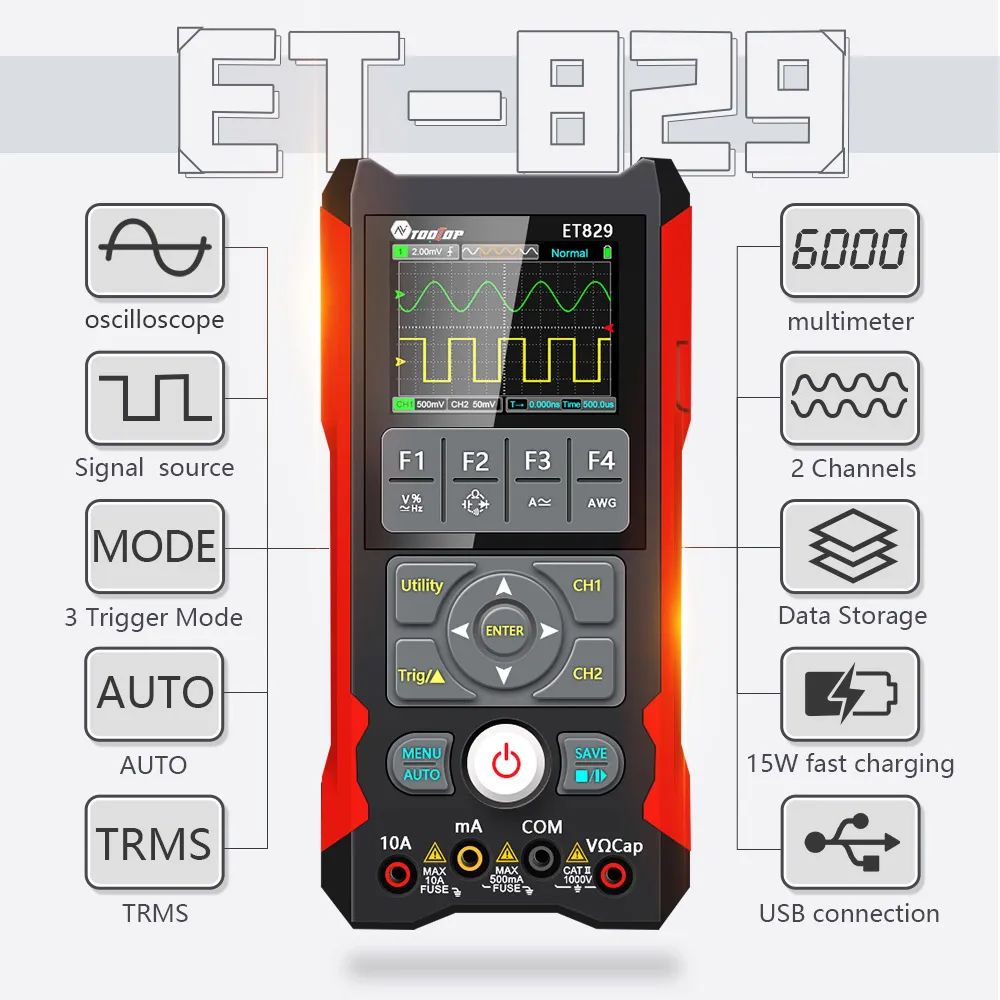
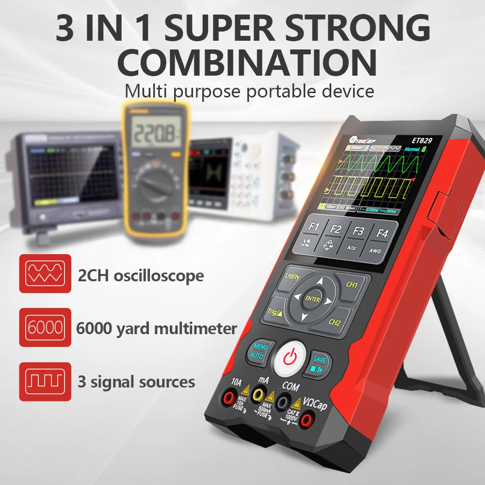
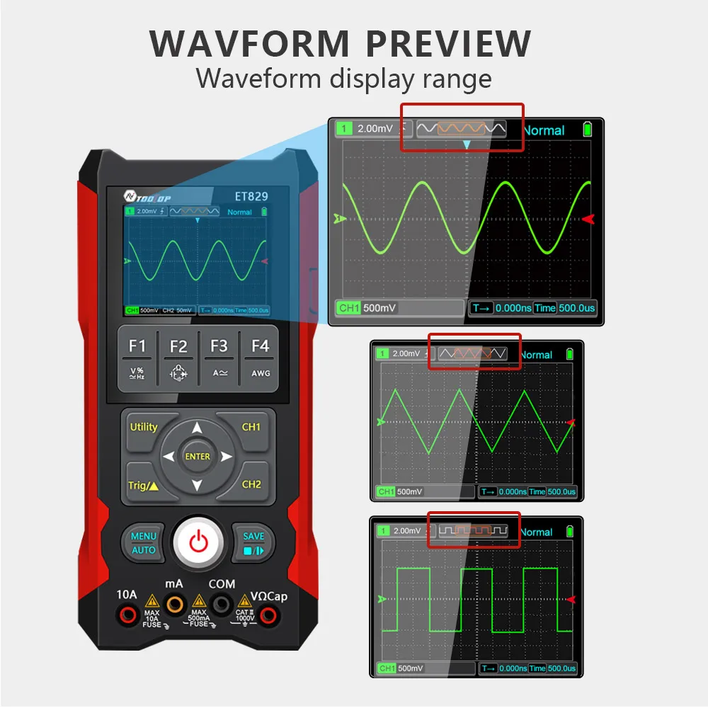
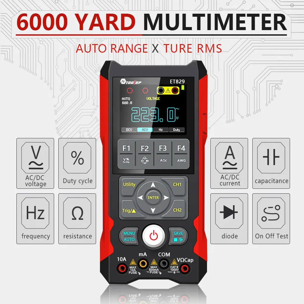
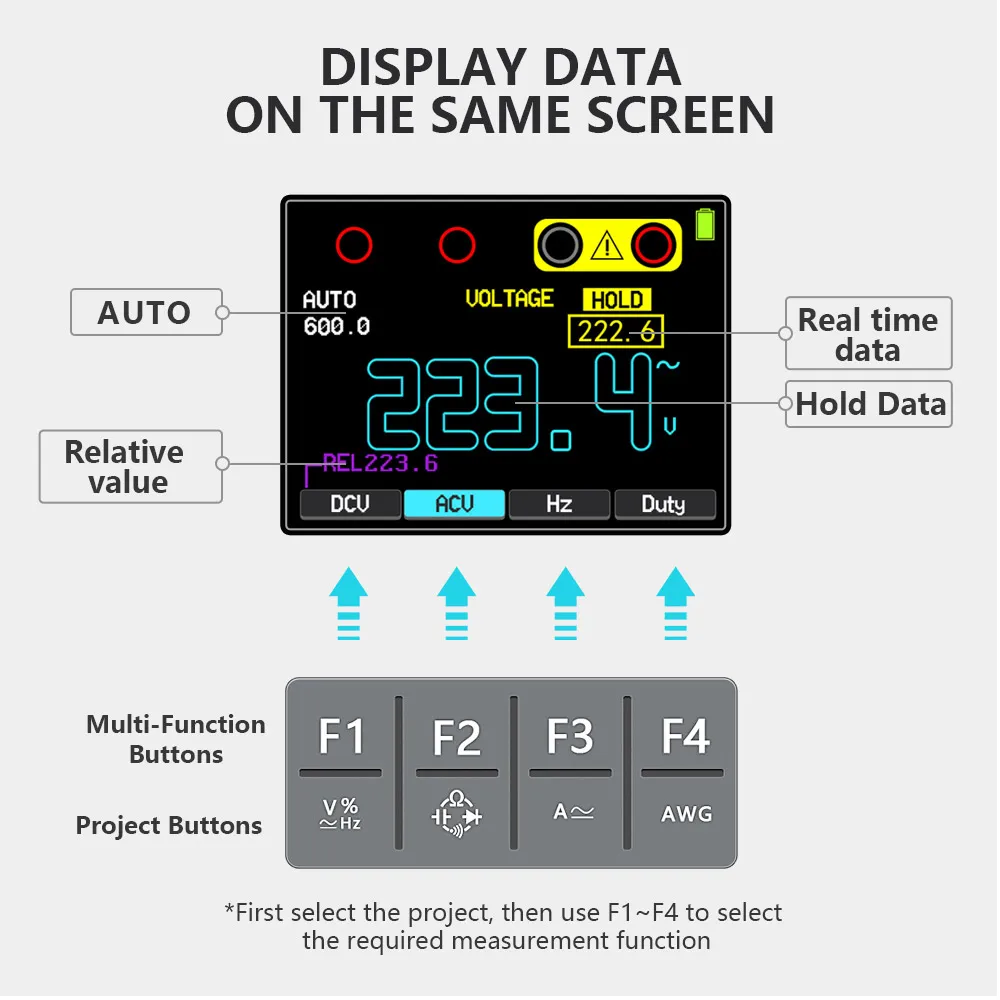
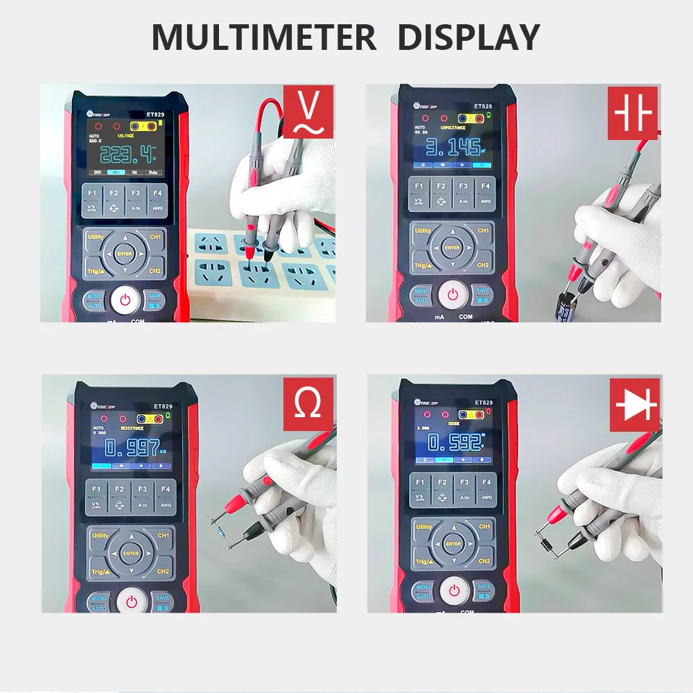
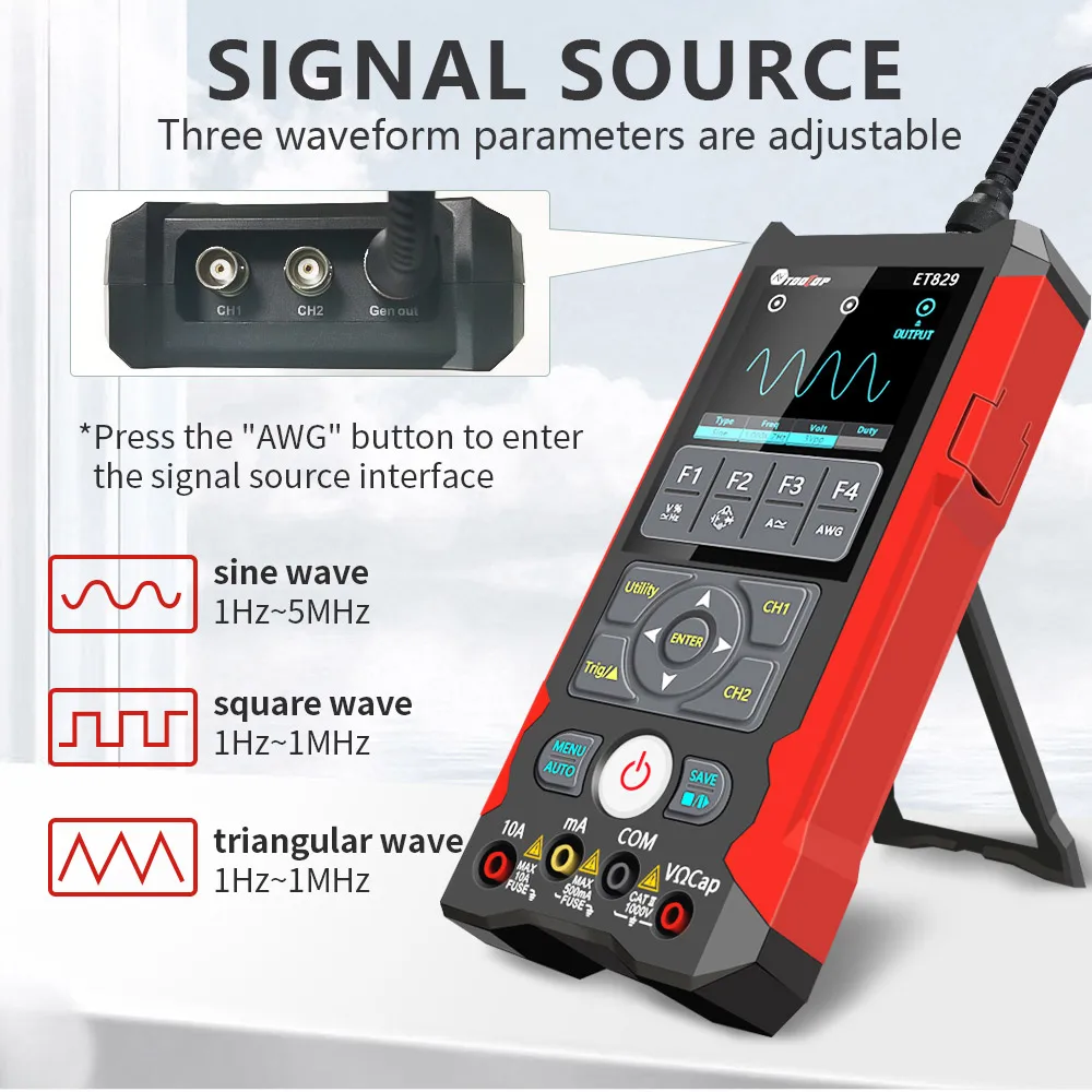
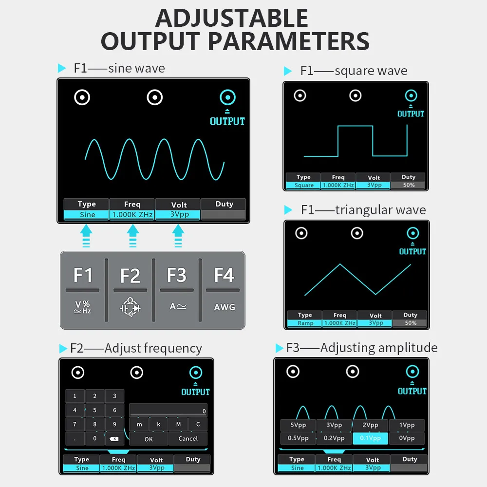
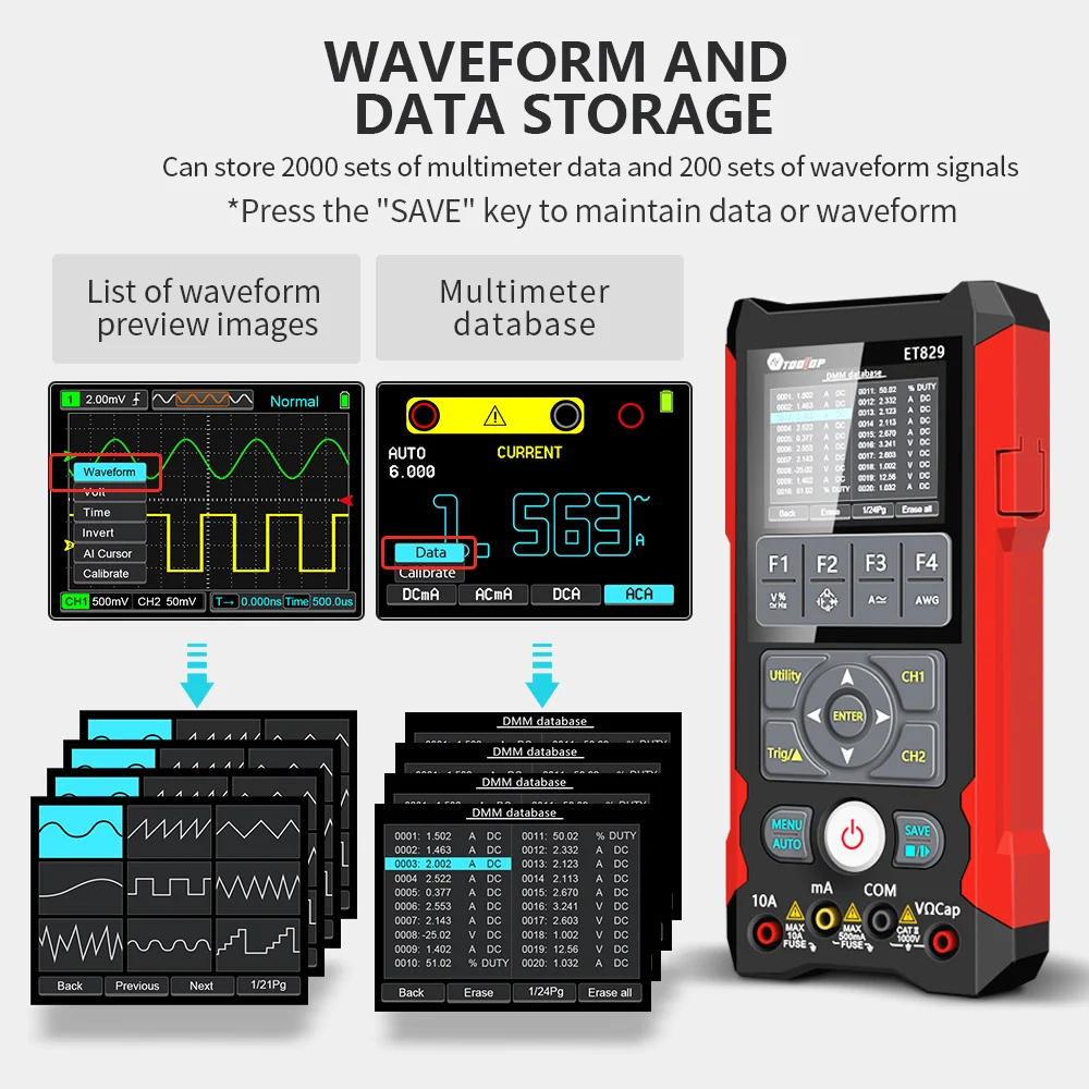
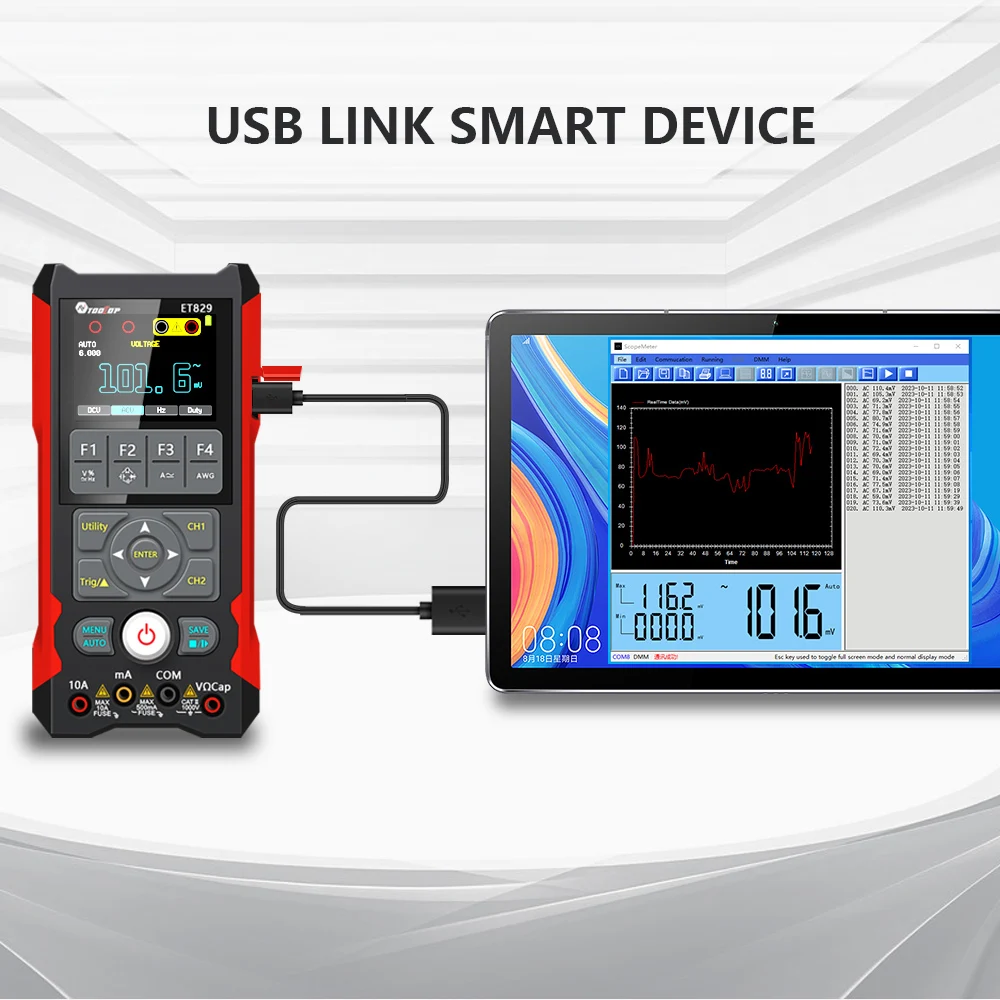
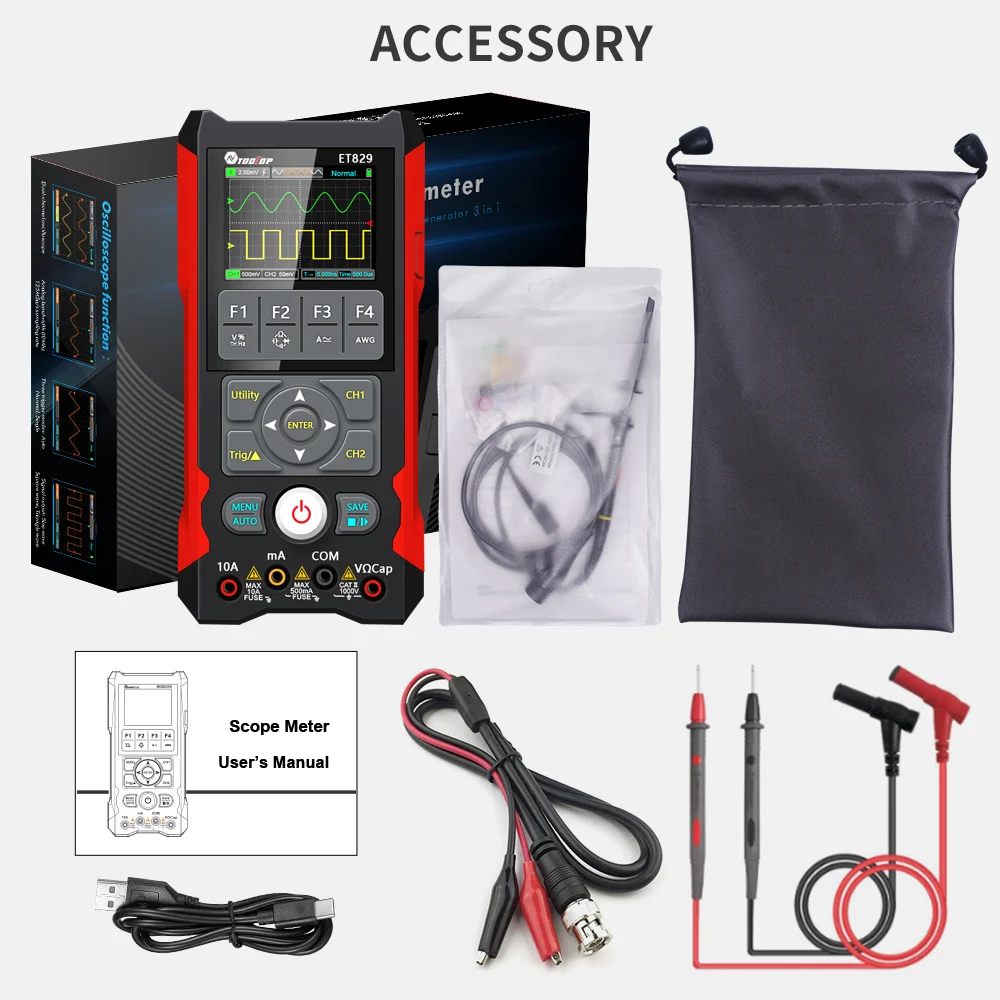
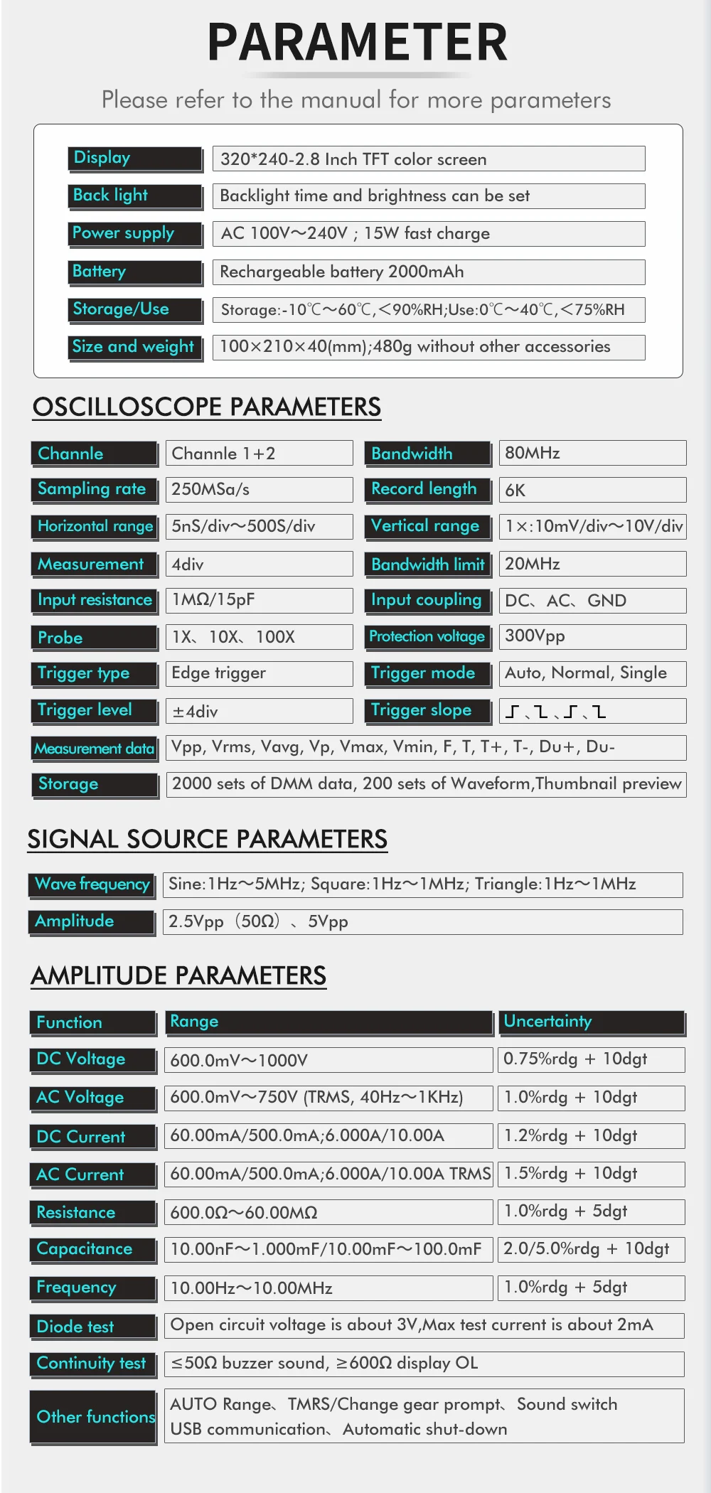
The TOOLTOP ET829 is a professional 3-in-1 testing instrument that combines an 80MHz Digital Storage Oscilloscope (DSO), a 6000-count True RMS Digital Multimeter, and a 1Hz–5MHz Signal Generator in one portable device. It is ideal for electronics repair, automotive diagnostics, power maintenance, laboratory testing, engineering, and field troubleshooting.
| Specification | Details |
|---|---|
| Brand | TOOLTOP |
| Model | ET829 |
| Product Type | 3-in-1 Digital Test Instrument |
| Country of Origin | China |
| Certification | CE |
| Display | 2.8-inch TFT Color LCD |
| Resolution | 320 × 240 |
| Digital Channels | 2 |
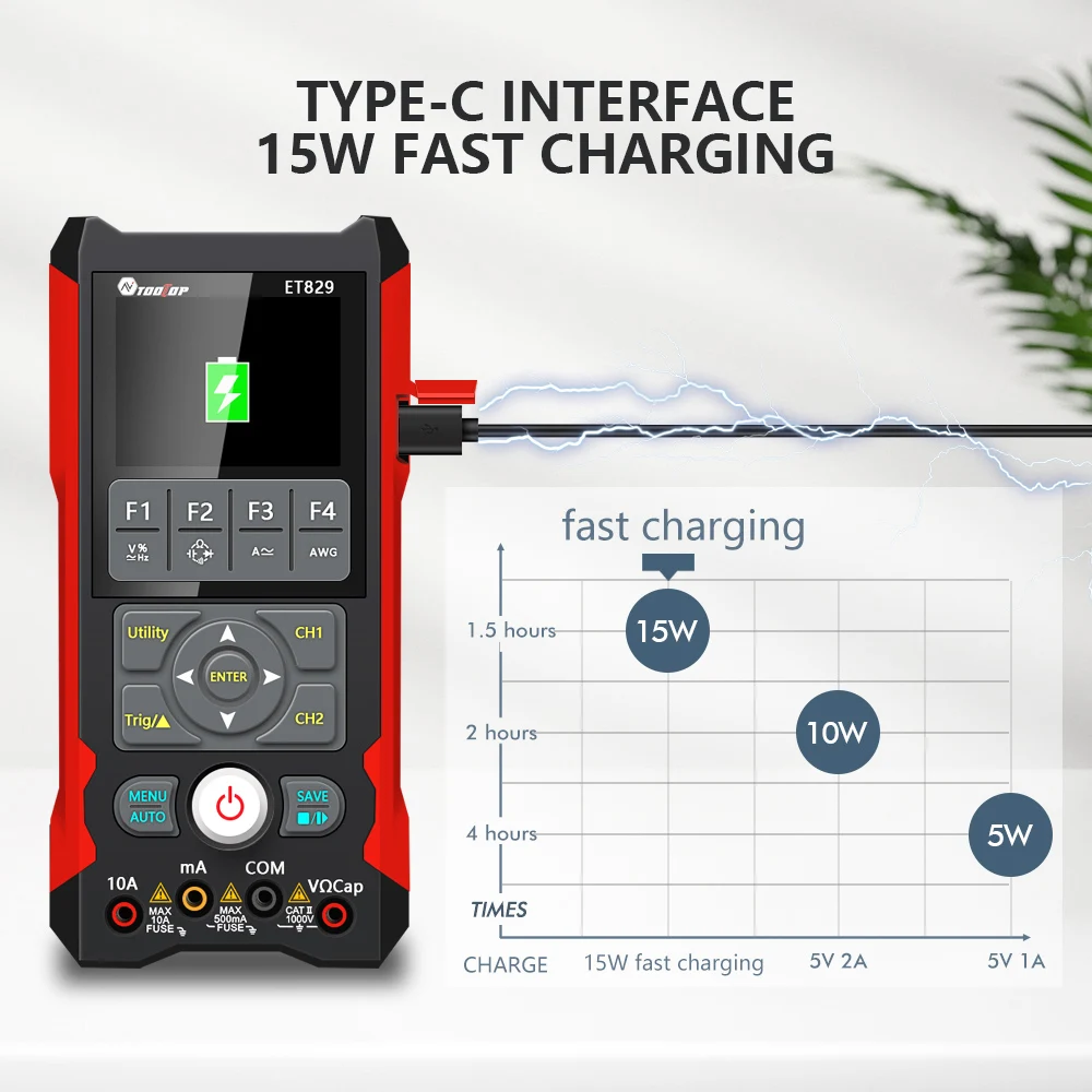
| Battery | 2 × 18650 Rechargeable Lithium Batteries |
Specifications | Details |
Battery Included | Yes |
High-Concerned Chemical | None |
Brand Name | TOOLTOP |
Origin | Mainland China |
Description:
This handheld portable network cable tester is a practical tool for all kinds of communication lines and engineering maintenance personnel. It helps you quickly and efficiently find the cable you need from a large number of cables.
Features:
Support 3 modes freely switch : POE mode, digital mode and analogs mode. POE testing function: Used for testing standard and non-standard POE device, it can also test POE voltage, power supplys polarity and power supplys mode Voltagee test function: You can click "V" to enter the voltage test function, which can measure the battery voltage and voltage polarity and you can press "V" again to enter the POE test mode. You can measure the POE power supplys line and voltage. Adjustable sensitivity:when receiving signal is strong, turn down the sound gear;when receiving sianal is weak, raise the sound gear, which can give you a more accurate testing data. With LED flashlight function:The flashlight can be turned on in the dark environment to make detection and search more convenient
Large LCD Screen,intuitive and clear display the test result
Widely Application: computers network, video network, optical communication engineering and other metal wire line occasions. Specifications: Material: ABS ype: ET612/ET613 (optional) Power: Transmitter: 3*AA battery (NOT INCLUDED) Receiver: 9V (NOT INCLUDED) Analogue cable tracing: √ Digitalized cable tracing: √ Tracking cables with PoE support: √ Identity wire peers & quality of wire connections: √ Battery voltage polarity checking: √ Battery Voltage measurment (for reference only): √ PoE voltage polarity checking: √ PoE Voltage measurment (for reference only): √ Split pair: √ Breakpoint checking: √ Continuity test: √ Tracing signal transmission distance: 3Km Output signals level: ~15Vp-p Vibration indication: ONLY ET613 Flashlight: √ Loudness adjustable: √ Low battery indicator: √ Package size: 220*148*50mm/8.7*5.8 * 2.0in Package weight: 389g / 13.7ounce
Notice:
1. Do not directly search for cables that have been connected to strong current (such as wires at home), otherwise it may cause personal injury and equipment damage.
2. The host LCD screen or line finder POWER light flashes, indicating that the battery voltage is low, please replace the battery Packing list: 1 * Transmitter 1 * Receiver 3 * Cables


